
What Is a Body Control Module in a Car?
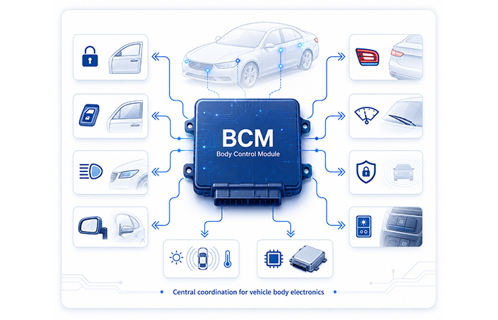
A Body Control Module, or BCM, is an automotive electronic control unit that coordinates many of your vehicle’s non-powertrain body and cabin electronics. It connects everyday functions such as door locks, power windows, lighting, mirrors, wipers, and security features so they can work together consistently. The BCM receives information from switches, sensors, and other ECUs, then helps the vehicle respond through its internal communication network. In simple terms, it acts as a central coordination point for many of the electrical features you use every day.
What Does BCM Stand For in a Car?
In a car, BCM stands for Body Control Module. It is a type of automotive electronic control unit designed around the vehicle’s body and cabin electronics, rather than the engine or transmission. The word “Body” refers to the electrical systems associated with the vehicle body, passenger compartment, access, comfort, and related equipment.
“Control Module” means that the BCM is more than a simple switch box. It contains electronic processing, communication, and control capabilities that allow it to receive information and coordinate responses within the vehicle. When you see terms such as BCM in a car, body control unit, or body module control, they usually refer to this same category of automotive controller.
In simple terms, the BCM is the electronic module associated with the vehicle’s body, cabin, and convenience electronics.
What Is the Role of a BCM in a Vehicle?
The BCM serves as a coordination hub for vehicle body electronics. It brings together body-related requests, operating states, and network information so that separate electronic systems can respond consistently. Instead of treating every switch, sensor, and local controller as an isolated device, the vehicle can use the BCM to organize how body-electronics information is shared.
Its exact position depends on the vehicle architecture. In some cars, the BCM acts as a central controller. In others, it works with door modules, lighting controllers, gateways, or zonal control units. This distributed approach allows different modules to share status information, diagnostic data, and network requests while still operating as one coordinated vehicle system.
The BCM is often described as a coordination hub for body electronics—not as the only “brain” in the entire vehicle.
Is a Body Control Module an ECU?
Yes. A Body Control Module is one type of automotive ECU. The term ECU stands for Electronic Control Unit and refers broadly to the electronic controllers used throughout a vehicle. It does not refer only to the computer that manages the engine.
Modern vehicles contain multiple ECUs, each assigned to a particular system or operating domain. An Engine Control Module manages engine-related operation, while a Transmission Control Module focuses on the transmission. Other controllers may be responsible for braking, battery management, safety systems, infotainment, or body electronics.
The BCM belongs within this wider ECU family. Its particular area is vehicle body and cabin electronics. This means that “BCM vs ECU” is not a comparison between two completely separate categories. Instead, the relationship is hierarchical: every BCM is an ECU, but not every ECU is a BCM.
Think of ECU as the general category and BCM as one specialized member of that category.
What Types of Systems Are Associated With the BCM?
A BCM is generally associated with the vehicle systems you interact with inside and around the cabin. These systems are often grouped into access and security, lighting, comfort and convenience, and vehicle coordination.
These categories help you understand the BCM’s general scope without assuming that every vehicle uses the same design. Depending on the architecture, a function may be coordinated by the central BCM, handled by a local door or lighting module, or shared across several electronic controllers.
This overview shows the main categories associated with a BCM without describing every individual function or control method. For a more complete function-by-function explanation, continue to What Does a Body Control Module Do?
Why Do Modern Cars Use a Body Control Module?
Modern cars use a Body Control Module because many body and cabin features need to exchange information and respond as one coordinated system. Without a central coordination point, door locks, lighting, windows, mirrors, sensors, and other electronic functions would require more separate control logic and more complicated wiring.
By bringing these requests and status signals together, the BCM helps reduce wiring complexity and allows several functions to share switch, sensor, and vehicle-status information. For example, one locking request may also affect the alarm status, interior lighting, window behavior, and confirmation indicators, depending on how the vehicle is configured.
This coordinated approach also supports more consistent diagnostics and makes it easier for manufacturers to configure different equipment packages on the same vehicle platform. A vehicle can use similar electronic hardware while enabling different body-electronics features for different models, trim levels, or regional requirements.
The BCM gives you a more integrated vehicle experience by helping separate body functions share information, diagnostics, and coordinated responses.
What Does a Body Control Module Look Like?
A Body Control Module in a car is usually a compact rectangular electronic unit protected by a plastic or metal housing. Its outer case may include mounting tabs, identification labels, ventilation details, and several multi-pin connectors for the vehicle wiring harness.
Inside the enclosure is a printed circuit board containing a microcontroller, power-management circuits, communication interfaces, and input and output electronics. These components allow the module to receive vehicle information, process requests, and coordinate body-related systems. The exact internal arrangement varies according to the number of connected functions and the vehicle’s electronic architecture.
Some BCMs are separate electronic boxes, while others are integrated into a fuse box, junction box, or larger electrical distribution assembly. Because size, connector layout, enclosure shape, and installation method differ between manufacturers and vehicle platforms, you cannot reliably identify a BCM by appearance alone.
The illustration below shows a typical BCM form factor, not a specific manufacturer or vehicle part number.
Where Is the BCM Located in a Car?
There is no universal location for a Body Control Module in a car. Its position depends on the vehicle platform, electrical architecture, available cabin space, and whether the module is installed as a separate control unit or integrated with another electrical assembly.
Common locations include behind or below the dashboard, near the passenger-compartment fuse box, behind the glove compartment, beneath the center console, or under a seat. In some vehicles, the BCM is integrated into an electrical junction box or fuse-and-relay assembly, which can make it look different from a separate rectangular control module.
Because these locations vary significantly between manufacturers and models, you should confirm the exact position through the vehicle service manual, wiring diagram, or official electrical documentation. The module should not be identified by location or appearance alone.
There is no universal BCM location. The diagram below shows common installation areas, not a fixed position for every vehicle.
How Does the BCM Relate to Other Control Modules?
A BCM does not operate as an isolated controller. It exchanges commands, operating states, and diagnostic information with other ECUs so that your vehicle’s body electronics can respond consistently. CAN and LIN networks are commonly used to carry this information between the BCM, central gateway, and local electronic modules.
Depending on the vehicle design, the BCM may coordinate some functions centrally while door modules, lighting controllers, seat modules, or other local units perform the related actions. This allows body-electronics responsibilities to be distributed without losing shared status, diagnostics, or vehicle-level coordination.
In newer vehicles, some traditional BCM responsibilities may also be incorporated into a body domain controller or distributed across zonal controllers. The name and physical arrangement may change, but the need to coordinate body-related information across the vehicle remains.
The BCM is one participant in a connected vehicle-control system, working with central and local modules rather than replacing every controller in the car.
For a deeper engineering view of the architecture, signal paths, network interfaces, recommended IC families, and BOM guidance, explore the complete Body Control Module (BCM) application guide.
Learn how BCM inputs, processing, communication, and outputs work together in How Does a Body Control Module Work?
What a BCM Usually Does Not Control
A Body Control Module is an important vehicle controller, but it is not responsible for every electronic system in your car. Its main role is associated with body, cabin, access, lighting, comfort, and related electrical coordination—not the complete operation of the powertrain, safety, battery, and driver-assistance systems.
Engine combustion, fuel delivery, and emissions control are normally handled by an Engine Control Module. Transmission shifting is managed by a Transmission Control Module, while traction-battery monitoring belongs to dedicated battery-management electronics. Airbag deployment logic and advanced driver-assistance processing are also assigned to specialized controllers designed for those specific functions.
Understanding this boundary helps you interpret the term BCM in a car more accurately. The BCM is a specialized ECU for body electronics, not a single controller that manages the entire vehicle.
The BCM coordinates body-related systems, while other major vehicle functions remain under the control of their own dedicated ECUs.
Can BCM Mean Something Else?
Yes. In most body-electronics discussions, BCM means Body Control Module. In battery-system discussions, however, BCM may also refer to Battery Control Module. The intended meaning depends on the vehicle subsystem, document, component category, and technical context in which the abbreviation appears.
Always check whether the discussion concerns body electronics or a battery system before interpreting the abbreviation BCM.
See the distinction more clearly in Body Control Module vs Battery Control Module .
FAQs About EV High-Voltage Safety Systems
These questions help you understand how HVIL monitoring, insulation supervision, contactors, pre-charge, active discharge and emergency isolation work together to protect an electric vehicle throughout startup, driving, shutdown and service.
01 What is an EV high-voltage safety system? +
An EV high-voltage safety system is a coordinated group of electrical, electronic and mechanical protection functions designed to detect faults, prevent unintended energization and isolate hazardous voltage when necessary. It commonly includes insulation monitoring, HVIL detection, contactors, pre-charge circuits, active discharge, fuses, crash-response devices and manual service disconnects.
02 How does an electric vehicle disconnect high-voltage power during a fault? +
When a critical fault is detected, the BMS or safety ECU evaluates the vehicle state before selecting the appropriate response. The system may command the battery contactors to open, stop torque production, activate a discharge circuit and prevent the high-voltage network from restarting. During a severe crash or high-current fault, some platforms may also use a pyrotechnic disconnect to physically interrupt the main current path.
03 What is the difference between HVIL and insulation monitoring? +
HVIL and insulation monitoring detect different types of risk. The high-voltage interlock loop checks whether monitored connectors, covers and service disconnects remain correctly positioned. An insulation monitoring device evaluates the electrical resistance between the high-voltage network and the vehicle chassis. Many architectures require both conditions to be healthy before allowing the main contactors to close.
04 What happens when the HVIL loop is broken? +
A broken HVIL loop indicates that a monitored connector, battery cover or service disconnect may no longer be in its expected position. Before startup, the system will typically block pre-charge and prevent the main contactors from closing. If the fault occurs during operation, the vehicle may reduce power, request a controlled stop or open the contactors, depending on the fault conditions and platform safety strategy.
05 Why do EVs need a pre-charge circuit? +
EV power electronics contain DC-link capacitors that may draw very high current if they are connected directly to the traction battery while discharged. A pre-charge circuit uses a controlled current path to raise the downstream bus voltage gradually before the main contactors fully connect the battery. This limits inrush current and reduces stress on contactors, fuses, connectors, busbars and power-electronic components.
06 Is opening the main contactors enough to make an EV safe? +
Not always. Opening the contactors separates the traction battery from much of the downstream high-voltage network, but capacitors inside the inverter, charger and other power electronics may retain hazardous voltage. Active or passive discharge circuits are used to reduce this residual energy, and technicians must still verify the voltage before beginning service work.
07 What is the purpose of a pyrotechnic fuse in an electric vehicle? +
A pyrotechnic fuse or disconnect provides an additional physical isolation mechanism for severe crash or high-current fault conditions. When activated, it irreversibly interrupts the main electrical path. It is particularly useful when conventional contactors may be mechanically damaged, welded closed or unable to provide sufficiently reliable isolation.
08 Why are high-voltage cables in electric vehicles orange? +
Orange insulation makes high-voltage cables and components visually distinguishable from conventional low-voltage wiring. It warns technicians and emergency responders that the circuit may present an electrical hazard. The colour is an identification measure, not proof that the circuit is energized, isolated or safely discharged.
09 How do technicians safely service an EV high-voltage system? +
Technicians follow a controlled depowering procedure that may include switching off the vehicle, preventing unintended restart, removing the manual service disconnect, waiting for the specified discharge period and verifying the absence of hazardous voltage with approved test equipment. Appropriate PPE, insulated tools and lockout procedures may also be required for the vehicle and task.
10 Can an EV high-voltage system remain dangerous after the vehicle is turned off? +
Yes. Turning off the vehicle does not automatically prove that every high-voltage component is de-energized. The traction battery still stores energy, downstream capacitors may remain charged and a damaged contactor may fail to open correctly. Safe servicing therefore requires physical isolation, discharge confirmation and direct voltage verification.
The essential principle is simple: never assume that a shutdown command, an open connector or a powered-off display proves the system is safe. High-voltage safety depends on isolation, controlled discharge and verified electrical measurements.