
Body Control Module vs Battery Control Module
In automotive electronics, BCM most commonly stands for Body Control Module . In electric vehicles , hybrid vehicles and battery-system documentation, however, BCM may also mean Battery Control Module . These are two different modules, and both may be present in the same EV or HEV.
A Body Control Module manages vehicle-body functions , while a Battery Control Module manages battery-pack condition, operating limits and safety .
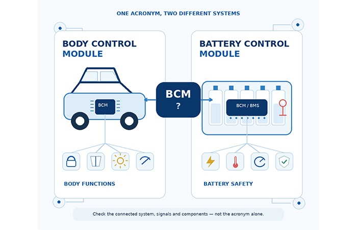
What Does BCM Mean in Automotive Electronics?
When you see BCM in a car, the abbreviation most commonly refers to a Body Control Module. This is especially likely when the surrounding document discusses doors, windows, mirrors, lighting, wipers, alarms, keyless entry or other body-electronics functions.
In electric-vehicle, hybrid-vehicle and battery-system documentation, however, BCM may instead refer to a Battery Control Module. You will normally see this meaning when the surrounding system involves battery cells, pack current, cell voltage, temperature, contactors, balancing or battery-state information.
Look at the connected system, measured signals and controlled components. A body BCM works with vehicle-body loads and user inputs, while a battery BCM works with battery measurements, operating limits and protection.
The name Battery Control Module is not used consistently by every vehicle manufacturer, battery supplier or semiconductor company. Depending on the system architecture, you may encounter several related terms:
These names may describe different levels of the battery-management architecture. You should therefore confirm the module’s actual inputs, outputs, connected components and responsibilities before treating the terms as interchangeable.
Body Control Module vs Battery Control Module at a Glance
The clearest way to separate the two modules is to compare their vehicle domains, measured signals, controlled systems, voltage environments and semiconductor requirements. Although both may be called BCM, they serve fundamentally different engineering purposes.
| Comparison | Body Control Module | Battery Control Module |
|---|---|---|
| Primary purpose | Coordinates body, comfort, access, visibility and low-voltage electrical functions. | Monitors, manages and protects the vehicle battery system. |
| Main vehicle domain | Body electronics. | Battery and electrified powertrain. |
| Typical voltage domain | Primarily 12 V or 24 V vehicle electrical systems. | Low-voltage control and sensing connected to a low-voltage or high-voltage battery system. |
| Typical monitored signals | Switch state, position, light, rain, latch and network commands. | Cell voltage, pack current, temperature, isolation and battery-status information. |
| Typical controlled systems | Doors, windows, mirrors, lighting, wipers, alarms and accessories. | Contactors, balancing circuits, cooling requests and charge or discharge limits. |
| Typical outputs | Network commands, lamps, relays, smart switches and small motors. | Contactor commands, balancing control, thermal requests and battery fault limits. |
| Main protection focus | Wiring faults, short circuits, overload, overheating and unintended load operation. | Overvoltage, undervoltage, overcurrent, unsafe temperature and cell imbalance. |
| Communication | LIN, CAN, CAN FD, GPIO and ADC interfaces. | CAN, SPI, isolated communication and battery-monitor daisy chains. |
| Typical IC categories | MCU, LIN/CAN transceiver, MSDI, smart load switch and system basis chip. | Battery-monitor AFE, current sensor, isolation IC, balancing circuit and contactor driver. |
| Relationship to BMS | Separate from the battery-management system. | Usually part of, or closely associated with, the battery-management system. |
| Typical vehicles | Internal-combustion, hybrid and electric vehicles. | Mainly hybrid, electric and other battery-powered vehicles. |
On smaller screens, swipe horizontally to view the complete comparison table.
Why the Voltage Domain Matters
A Body Control Module normally operates within the vehicle’s 12 V or 24 V low-voltage electrical system. Its hardware must tolerate conditions such as cold crank, load dump, jump start and noise from long wiring harnesses.
A Battery Control Module may also use low-voltage control circuitry, but its sensing and communication interfaces can be connected to a high-voltage traction battery and series-connected cell stack. This creates additional requirements for measurement accuracy, electrical isolation and safe contactor control.
The Core Difference: What Each Module Observes, Decides and Controls
You can understand the difference between the two modules more clearly by following the same three questions: What does the module observe, what decisions does it make, and what does it control? A Body Control Module responds mainly to vehicle-body inputs and user requests, while a Battery Control Module evaluates battery condition, operating limits and safety.
This distinction is more useful than a simple feature list because it shows you how each controller fits into the vehicle’s decision chain. One module translates switches, sensors and body-network messages into body-function commands. The other translates cell voltage, pack current, temperature and isolation information into battery limits, contactor commands and fault responses.
How Their Inputs, Outputs and Power Domains Differ
The two controllers require different circuits because they receive different signals and operate in different electrical environments. A Body Control Module collects many low-voltage discrete, analogue and network inputs distributed across long vehicle harnesses. It then drives lamps, relays, motors or local body modules.
A Battery Control Module instead handles high-accuracy, multi-channel battery measurements. Its control electronics may use low-voltage power, but its sensing interfaces can be connected to a series cell stack, high-voltage contactors and isolated battery-monitor communication. That is why the two modules need very different analogue front ends, protection circuits and semiconductor categories.
| Design Area | Body Control Module | Battery Control Module |
|---|---|---|
| Input sources | Switches, sensors, latch signals and body-network messages. | Cell taps, current sensors, temperature sensors and isolation signals. |
| Input characteristics | Many low-voltage discrete and analogue signals carried through long wiring harnesses. | High-accuracy, multi-channel measurements associated with a battery stack. |
| Output types | Smart load switches, relays, lamps, motors and network commands. | Contactor commands, balancing outputs, power limits and thermal requests. |
| Power environment | A 12 V or 24 V automotive supply exposed to load dump, cold crank and jump start. | A battery-pack environment requiring precision sensing and often electrical isolation. |
| Communication | LIN, CAN, CAN FD and local GPIO or SPI interfaces. | CAN, isolated SPI, daisy-chain or isolated battery-monitor communication. |
| Diagnostic focus | Open load, short to ground, short to battery, overcurrent and thermal shutdown. | Cell overvoltage, undervoltage, overcurrent, overtemperature, imbalance and isolation faults. |
On smaller screens, swipe horizontally to view the complete engineering comparison.
What Is a Body Control Module?
A Body Control Module is an automotive electronic control unit that coordinates distributed vehicle-body functions. It works across broad system groups such as body access, comfort, lighting and visibility, security and low-voltage accessory control. Its role is not limited to switching one device. It combines user inputs, sensor information and vehicle-network messages to coordinate how multiple body functions operate together.
Depending on the vehicle architecture, the module may directly drive lamps, relays or small motors through smart high-side and low-side switches. It may also send commands through LIN or CAN to door modules, lighting modules and other local controllers. This combination of direct load control and network coordination allows one BCM to supervise many distributed functions without requiring every load to connect directly to the central ECU.
A Body Control Module can also influence the vehicle’s 12 V battery consumption by coordinating sleep, wake-up, delayed accessory shutdown, standby current and low-voltage load disconnection. However, it does not normally perform cell-level voltage monitoring, SOC estimation or battery-cell balancing.
For the complete ECU architecture, load-driver design rules and recommended IC categories, see Body Control Module (BCM) – Car Body Electronics .
What Is a Battery Control Module?
A Battery Control Module is a controller or monitoring module used within a vehicle’s battery-management architecture. Its exact role depends on the vehicle type and the terminology used by the manufacturer. In a conventional internal-combustion vehicle, the 12 V battery may instead be supervised by an intelligent battery sensor, alternator controller, energy-management ECU or another power-management function. A separate, complex module explicitly called a Battery Control Module may not exist.
In hybrid and electric vehicles, the Battery Control Module is normally associated with the high-voltage Battery Management System. It receives measurements such as individual cell or module voltage, pack current, battery temperature and isolation status. These signals help the system identify unsafe operating conditions and determine whether charging, discharging or continued battery operation should be limited.
The module may support State of Charge, State of Health, available-power and charge or discharge-limit calculations. These are estimated values based on measurements and models rather than perfectly exact readings. It may also coordinate main contactors, pre-charge requests, cooling or heating requests, balancing commands and battery-fault reporting.
The term may describe the central controller within a BMS, a local battery-monitoring module, or a supplier-specific part of the wider battery-management architecture. You should confirm the module’s real inputs, outputs and system position before assuming the names are interchangeable.
How Their IC Requirements Differ
Once you separate the two BCM meanings, the semiconductor requirements become much easier to understand. A Body Control Module must communicate across the vehicle network, collect many switch and sensor inputs, and safely drive distributed low-voltage loads. A Battery Control Module must measure battery conditions accurately, maintain separation between electrical domains and coordinate battery-protection functions.
The difference is not simply that one module controls windows while the other monitors cells. Their input interfaces, output stages, current-measurement methods, isolation requirements, communication paths and power-management circuits are built around fundamentally different electrical environments.
Specific part numbers, vendor recommendations, parameter tables, BOMs, prices, stock and replacement options should be evaluated in dedicated Body Control Module and Battery Management System application pages.
On smaller screens, swipe horizontally to review the complete functional-block comparison.
How to Tell Which BCM a Datasheet, Schematic or BOM Refers To
When a datasheet, schematic or component list uses only the abbreviation BCM, you can usually identify the intended module without relying on the document title. Start with the connected components, then check the signal names, connector labels and IC categories.
This four-step process is especially useful when you receive an incomplete automotive BOM, partial schematic, RFQ or component cross-reference request. Each individual clue may be ambiguous, but the combined pattern normally makes the module type clear.
A CAN interface can appear in both modules. The stronger evidence comes from what the controller measures, what it drives and whether the surrounding circuitry is built for body loads or battery-pack monitoring.
On smaller screens, swipe horizontally to follow the complete four-step identification process.
When the document is built around switch inputs, lamps, motors, relays, LIN nodes and smart load switches, it most likely refers to a Body Control Module. When it is built around cell taps, current sensing, contactors, isolation, battery-monitoring AFEs and balancing circuits, it most likely refers to a Battery Control Module.
Is a Battery Control Module the Same as a BMS?
A Battery Management System normally describes the complete combination of sensing, control, communication, protection and software used to manage a battery pack. A Battery Control Module may refer to the central controller inside that system, a local monitoring board or a supplier-specific name for the complete control assembly.
When you see the term Battery Control Module, you should not assume that it always represents the entire BMS. Vehicle manufacturers, battery-pack suppliers and semiconductor companies may use the same name for different levels of the battery-management architecture.
The most reliable approach is to identify what the module measures, what decisions it makes and where it sits in the system. In practice, the term usually refers to one of three configurations.
The module may act as the central controller responsible for data processing, SOC and SOH estimation, fault decisions, CAN communication and contactor coordination.
In a distributed BMS, it may refer to a local board installed near a battery module. Its main role may be limited to cell-voltage measurement, temperature monitoring and balancing-status reporting.
Some suppliers use names such as Battery Control Module, Battery Control Unit or BMS Controller for the complete battery-control assembly.
To determine which meaning applies, check the module’s input signals, controlled outputs, system block diagram, communication path and physical installation location. These details will tell you whether you are looking at a complete BMS, its central controller or a local battery-monitoring module.
Can an EV or Hybrid Have Both Modules?
The two controllers operate in different vehicle domains. They may exchange information through the vehicle network, but neither module replaces the other.
Electrification does not remove the need for a Body Control Module. An EV or hybrid still needs coordinated control of body access, windows, lighting, wipers, security and comfort functions. These systems may be managed by a central BCM, distributed body controllers or newer zone and domain controllers.
At the same time, the high-voltage traction battery requires a Battery Control Module or Battery Management System to monitor battery condition, calculate operating limits, coordinate contactors and protect the battery from unsafe voltage, current or temperature conditions.
The two modules may communicate through CAN, CAN FD or automotive Ethernet with the Vehicle Control Unit, gateway, domain controller or thermal-management controller. For example, a battery controller may report available power, while the body controller continues to manage access, lighting and low-voltage accessory behaviour.
Coordinates doors, windows, lighting, access, wipers and comfort functions across the low-voltage body-electronics system.
Manages traction-battery monitoring, charge and discharge limits, contactors, temperature and battery safety.
Does the Body Control Module Manage the Car Battery?
A Body Control Module can reduce unnecessary 12 V battery drain by coordinating when accessories wake, sleep or shut down. A Battery Control Module, by contrast, monitors battery condition and determines whether the battery can safely charge, discharge or remain connected.
The confusion occurs because both modules can influence how electrical energy is used in the vehicle. The difference is the level at which they operate. The Body Control Module manages low-voltage body loads and accessory behaviour, while the Battery Control Module manages battery measurements, operating limits and pack safety.
For example, the Body Control Module may place door, lighting or comfort electronics into sleep mode after the vehicle is locked. It may delay accessory shutdown, disconnect non-essential loads during a low-voltage condition or coordinate with an energy-management ECU. These actions help protect the 12 V supply from avoidable parasitic drain, but they do not measure the condition of individual battery cells.
Cell-level functions such as cell-voltage monitoring, pack-current measurement, temperature supervision, SOC and SOH estimation, balancing and contactor control belong to the Battery Control Module or the wider Battery Management System.
Accessory sleep and wake-up, delayed shutdown, quiescent-current reduction, low-voltage load shedding, battery-drain prevention and coordination with an energy-management ECU.
Cell voltage, pack current, battery temperature, SOC, SOH, cell balancing, contactors and battery safety limits.
Which Automotive BCM Are You Looking For?
The correct application path depends on whether your design is built around vehicle-body loads and networked accessories or around battery-pack measurements, contactors and protection. Use the signals, connected components and IC categories in your schematic or BOM to choose the relevant engineering topic.
These two application areas may communicate inside the same vehicle, but their architectures, electrical environments and semiconductor requirements are different. Select the path that matches the system you are designing or sourcing.
Choose this path when you are working with door and window control, lighting and load control, LIN/CAN body networking, switch detection, smart high-side or low-side drivers and body-ECU power management.
Choose this path when you are working with cell-voltage monitoring, pack-current sensing, battery-temperature monitoring, isolation, cell balancing, contactor control and battery-management ICs.
FAQs About Body and Battery Control Modules
These answers help you distinguish a Body Control Module from a Battery Control Module when the same BCM abbreviation appears in a vehicle document, schematic, datasheet or BOM.
What does BCM stand for in a car? +
In most automotive contexts, BCM stands for Body Control Module. In EV, hybrid and battery-system documentation, it may also mean Battery Control Module. Check the connected system and signals rather than relying on the abbreviation alone.
Is a Body Control Module the same as a Battery Control Module? +
No. A Body Control Module coordinates vehicle-body electronics such as access, lighting and comfort functions. A Battery Control Module monitors battery condition, operating limits and safety.
Is a Battery Control Module the same as a BMS? +
Not necessarily. A Battery Control Module may be the central BMS controller, a local battery-monitoring module or a supplier-specific name for the complete BMS control assembly. Confirm its inputs, outputs, communication and installation position.
Can an EV have both a Body Control Module and a Battery Control Module? +
Yes. An EV or hybrid can use both modules. The Body Control Module manages body-electronics functions, while the Battery Control Module manages traction-battery condition and safety. They may exchange information through the vehicle network, but they cannot replace each other.
Does the Body Control Module monitor battery cells? +
Normally, no. A Body Control Module may manage 12 V accessory power, sleep and wake-up behaviour, but cell voltage, battery temperature and balancing are normally handled by the Battery Control Module or BMS.
Can a Body Control Module affect 12 V battery drain? +
Yes. Unexpected wake-up, accessories that do not enter sleep mode or loads that remain active can increase 12 V quiescent-current consumption. This is still different from cell-level battery monitoring and management.
How can I tell which BCM a datasheet refers to? +
Check the connected components, signal names, IC categories and system diagram. Lamps, switches, motors and LIN body nodes usually indicate a Body Control Module. Cell taps, battery-monitoring AFEs, contactors and isolation circuits usually indicate a Battery Control Module.
Which ICs are used in each type of BCM? +
A Body Control Module commonly uses an automotive MCU, LIN or CAN transceivers, MSDI devices and smart load switches. A Battery Control Module commonly uses battery-monitoring AFEs, precision current sensing, isolated communication and contactor drivers.