
Why DDR5 Memory Stability Depends on On-DIMM Power Management
DDR5 places the final stage of voltage conversion directly on the memory module. For you, that means memory reliability now depends not only on DRAM quality and signal timing, but also on how the DIMM generates its local power rails, responds to rapid load changes, controls startup sequencing, manages heat, and records fault evidence.
The central point: an on-DIMM PMIC can improve local voltage control and fault visibility, but it also introduces new challenges involving thermal density, rail sequencing, switching noise, protection behavior, and DIMM-level power integrity.
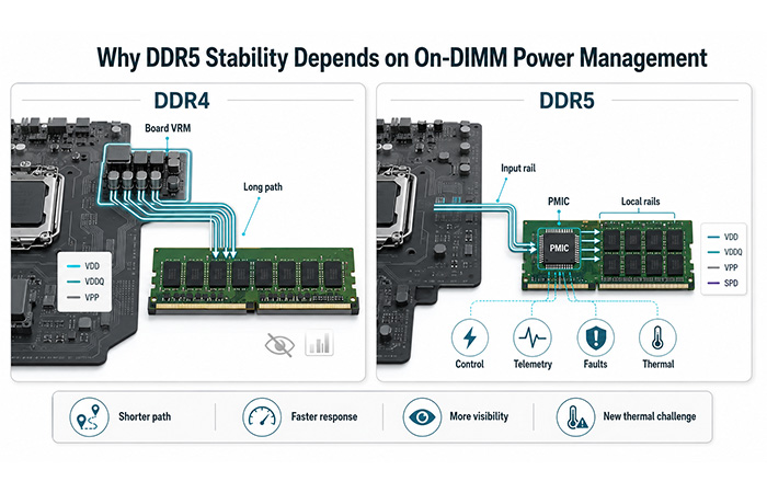
DDR5 Stability Is Also a Power-Delivery Problem
DDR5 memory stability depends heavily on on-DIMM power management because the final stage of voltage conversion is placed directly on the memory module. This shortens the electrical path between the regulator and the DRAM devices, improves the response to rapid load changes, enables more precise control of multiple power rails, and provides telemetry that helps you identify voltage, current, and thermal faults. However, placing the PMIC on the DIMM also introduces new thermal, sequencing, and power-integrity challenges.
Modern Data Center & Servers platforms depend on large DDR5 memory populations to support artificial intelligence, cloud computing, virtualization, high-performance computing, databases, and other data-intensive workloads. As memory speed and module density increase, smaller voltage, timing, and temperature margins can have a greater effect on system reliability.
When a system experiences an intermittent boot failure, memory-training retry, workload-dependent error, unexplained reset, or loss of PMIC telemetry, you need to look beyond the memory chips themselves. The real question is whether the failure began with a power-rail transient, an incorrect startup window, thermal derating, protection entry, or a management-rail communication problem.
What you will be able to understand
What a DDR5 on-DIMM PMIC actually controls
Why DDR5 moved final voltage regulation onto the DIMM
How local regulation improves transient and rail control
How DDR5 differs from DDR4 motherboard-side regulation
Why voltage, load, temperature, and overclocking can expose instability
How to connect a memory symptom to power, thermal, or sequencing evidence
Why Does DDR5 Use an On-DIMM PMIC?
DDR5 uses an on-DIMM PMIC so the final low-voltage rails can be generated and controlled close to the DRAM devices. This shorter local path helps the module respond more effectively to rapid changes in current demand, coordinate multiple rails during startup and shutdown, and provide module-level voltage, current, temperature, and fault information. It also makes final-stage regulation more consistent across different platform designs, although it does not remove the influence of motherboard input power, DIMM layout, decoupling, airflow, or system cooling.
Shorter electrical distance between regulation and the DRAM load
Faster response to burst current and load transitions
Local generation and supervision of multiple DDR5 rails
Controlled sequencing, ramp behavior, and shutdown order
Voltage, current, temperature, warning, and fault telemetry
More repeatable module-level power behavior across platforms
Keep in mind: The PMIC improves your control over the power delivered to the DIMM, but stable operation still requires a clean input supply, correct layout, effective decoupling, sufficient airflow, and properly validated thermal behavior.
From Motherboard-Centric Regulation to On-Module Power Control
To understand why DDR5 memory stability depends more heavily on local power management, you first need to look at where the final memory voltages are generated. The most important architectural change is not simply a lower operating voltage. It is the movement from a largely motherboard-centric power architecture to a locally controlled power domain on the memory module.
In a typical DDR4 platform, the motherboard generates the key memory supply voltages through its own voltage-regulation circuitry. Those low-voltage rails must then travel across motherboard traces, through the DIMM connector, and finally into the memory module. The DIMM primarily receives and consumes those rails, while most regulation decisions remain on the motherboard.
This means the quality of the DDR4 motherboard VRM, the electrical length of the power path, connector impedance, and motherboard layout can all influence the voltage that eventually reaches the DRAM devices. If a fault occurs, you may see a memory-training failure or workload-related error without having detailed DIMM-level evidence explaining what happened to the power rail.
Regulation remains primarily on the motherboard
Key memory voltages are normally generated by the motherboard.
Low-voltage rails travel through board traces and the DIMM connector.
The memory module acts mainly as a load rather than a local power domain.
DIMM-level power telemetry and fault visibility are relatively limited.
DDR5 changes this arrangement. The motherboard still provides an input supply to the memory module, but the final conversion into the lower voltages required by the DRAM devices happens on the DIMM itself. The PMIC sits close to the load, creates several local rails, controls their startup behavior, monitors operating conditions, and applies protection when electrical or thermal limits are exceeded.
Final power conversion moves onto the memory module
The motherboard supplies an intermediate input rail to the DIMM.
Final low-voltage conversion is completed locally on the module.
The PMIC is positioned close to the DRAM devices and local decoupling.
Rail sequencing, monitoring, protection, and fault reporting become module-level functions.
DDR4 Motherboard VRM vs DDR5 On-DIMM Power Control
| Engineering dimension | DDR4 approach | DDR5 approach |
|---|---|---|
| Final voltage regulation | Primarily motherboard-side | On the memory module |
| Distance from regulator to DRAM | Longer electrical path | Shorter local path |
| Module-level rail control | Limited | Multi-rail local control |
| Sequencing visibility | Mostly platform-dependent | PMIC-controlled and observable |
| Fault telemetry | Limited at DIMM level | Voltage, current, temperature, and fault status |
| Platform dependency | Greater dependence on motherboard design | Reduced final-stage dependence |
| Local heat generation | Lower on-DIMM conversion heat | PMIC becomes a local heat source |
| Debug capability | Symptoms often inferred indirectly | Fault and state evidence may be readable |
DDR5 on-module power control does not make the motherboard irrelevant. DDR5 reduces the DIMM’s dependence on motherboard-generated final rail voltages, but the quality of the input supply, connector, grounding, platform sequencing, and overall power design still matters.
What Is a DDR5 On-DIMM PMIC?
More Than a Simple Voltage Regulator
A DDR5 PMIC (on-DIMM) locally converts the module’s input supply into the lower-voltage rails required by the DRAM devices, while also managing sequencing, monitoring, protection, and fault reporting.
When you evaluate a DDR5 PMIC, it helps to stop thinking of it as one regulator with one output. It is better understood as a coordinated power-management system containing conversion stages, rail controls, sensors, configuration logic, communication registers, and protection responses.
What the PMIC manages on the memory module
The Two Paths You Need to Understand
A useful way to understand the PMIC is to separate its work into a power path and an evidence path. These paths operate together, but they answer two different engineering questions.
Power Path
This is the physical path that receives the module input supply, converts it, and delivers usable voltage to the memory devices.
Input supply → PMIC conversion
VDD · VDDQ · VPP · management rail
Local rails → DRAM and management loads
Evidence Path
This is the information path that helps you determine which rail, condition, or protection response caused the instability.
ADC sampling → status registers
Fault bits · ALERT# · PMIC state
I²C/SMBus → event snapshot and system log
“One path powers the memory; the other explains what happened when that power became unstable.”
Why On-DIMM Power Management Improves Stability
The Six Main Stability Advantages
Locating final-stage regulation on the DIMM gives the memory module greater control over how its critical rails are generated, started, monitored, and protected. For you, the practical benefit is not simply a lower nominal voltage. It is a more local and measurable power-delivery system that can respond to changing memory activity with less electrical distance between the regulator and the load.
Shorter Electrical Distance to the DRAM Load
When the final regulator is located on the DIMM, the low-voltage rails travel a shorter electrical distance before reaching the DRAM devices. This can reduce the influence of PCB trace resistance, interconnect inductance, connector-related impedance, and other parasitic effects that become increasingly important during rapid changes in memory current.
A shorter local path also makes it easier to place decoupling close to the load and control the relationship between the PMIC, the output capacitors, the return path, and the DRAM devices. This does not eliminate voltage droop or switching noise, but it removes one major source of uncertainty from long-distance low-voltage distribution.
The practical meaning: shorter distance reduces one major source of impedance and gives you greater control over the local DIMM power-delivery network.
However, physical distance is only one part of stability. A poorly routed return path, inadequate control-loop margin, or badly positioned decoupling capacitor can still produce droop, overshoot, ringing, or rail-to-rail coupling even when the PMIC is physically close to the DRAM.
This is why capacitor placement can matter as much as nominal capacitance. A large capacitor located too far from the high-current path may provide less support during a fast transient than a smaller component placed close to the PMIC output and the critical DRAM load.
Faster Response to Transient Loads
Your DDR5 module does not draw a fixed amount of current throughout operation. Its power demand changes continuously as the system initializes memory, trains timing parameters, activates banks, transfers data, and responds to changing workloads. Some of these changes happen quickly enough that an average voltage reading cannot show what the DRAM devices actually experienced.
This is why DDR5 voltage stability depends heavily on the transient response of both the PMIC and the local DIMM power-delivery network. The rail must remain inside its operating margin not only during steady activity, but also during the brief transition between one load condition and another.
Where rapid current changes come from
When current demand rises suddenly, the local power system must supply the additional energy without allowing the rail to fall below its usable margin. When demand drops, it must prevent excessive overshoot. In both directions, the PMIC control loop, output capacitors, PCB layout, return path, and DRAM load operate as one electrical system.
“A rail can appear correct on a multimeter and still become unstable during a fast load transition.”
This explains why a system may look completely normal at idle yet experience DDR5 crashes under load, memory-training retries, intermittent errors, or resets during a stress test. A multimeter shows an averaged value. It does not reveal a short droop, overshoot, or oscillation that occurred during a rapid current transition.
More Precise Multi-Rail Control
DDR5 stability is not determined by one supply voltage alone. Your memory module depends on several rails serving different electrical functions, and each rail can react differently to load, temperature, startup timing, and protection thresholds.
The PMIC must therefore coordinate more than voltage conversion. It must keep the complete DDR5 multi-rail power system inside a valid operating window while the module moves between startup, active operation, fault response, recovery, and shutdown.
What precise rail control requires
Different rails have different failure personalities
Better Module-to-Module Consistency
Moving final-stage regulation onto the DIMM gives the module designer more direct control over the power rails that reach the DRAM devices. This can improve consistency between modules because the most sensitive low-voltage conversion is no longer performed entirely by a motherboard-side regulator located farther from the load.
For you, the benefit is a more repeatable DDR5 module power environment. The PMIC, local decoupling, rail configuration, protection rules, and monitoring behavior can be designed and validated as part of the memory module rather than being determined only by the host board.
The PMIC input supply still comes from the motherboard. A platform-level voltage sag, connector problem, grounding issue, or input transient can still cause the PMIC to enter an undervoltage condition or collapse one or more local rails.
On-DIMM regulation reduces dependency; it does not remove it.
Controlled Power Sequencing
A correct final voltage does not prove that the rail started correctly. During DDR5 initialization, stability also depends on when each rail begins to rise, how quickly it reaches its target, how related rails track one another, and when the module declares that power is ready.
The PMIC must coordinate soft-start, ramp control, rail tracking, PG/READY decisions, pre-bias handling, and power-down behavior. A mismatch in any of these windows can produce a repeatable electrical failure that appears random at the system level.
The startup sequence you need to validate
Startup symptoms that point to a sequencing window
Cold boot fails but warm reboot works
The first boot fails but the second boot succeeds
The DIMM initializes only after a full power cycle
The rail looks normal after boot, but startup fault flags remain
These conditions are often linked to residual voltage, pre-bias, incorrect ramp slope, a power-good decision made too early, or incomplete discharge during shutdown. The failure may disappear after the rails recover, but the original timing problem remains.
Module-Level Telemetry and Fault Reporting
One of the most important differences between a DDR5 PMIC and a basic voltage regulator is observability. The PMIC can provide evidence about rail conditions, temperature, protection events, and operating state instead of forcing you to infer every power problem from a downstream memory symptom.
This turns DDR5 fault telemetry into a practical debugging tool. When a DIMM fails to initialize, resets under load, or becomes unstable as temperature rises, the PMIC may preserve enough information to identify which rail or protection response was involved.
Evidence you may be able to read or record
Continuous Telemetry
Continuous readings help you understand sustained operating behavior and long-term trends.
Fault Snapshot
A fault snapshot helps you understand a short event that may be gone before the next scheduled read.
Continuous telemetry is valuable, but it has limits. The internal ADC may update more slowly than the electrical event, and host polling may occur only after the PMIC has recovered. A short undervoltage or overcurrent event can therefore disappear before the system reads the registers.
Polling can also miss an ALERT# transition, and a reboot may clear the exact state that would have explained the failure. For this reason, your logging process should capture the first available fault state before attempting recovery.
Snapshot first, reset later.
Save the rail identity, fault type, PMIC state, ALERT# cause, and available voltage, current, and temperature data before a reboot or register clear removes the original evidence.
Power Integrity vs Signal Integrity
Does the DDR5 PMIC Improve Signal Integrity?
The most accurate answer is that a DDR5 PMIC primarily improves power integrity, not signal integrity directly. It generates and supervises the supply rails that allow the DRAM core and I/O circuits to operate, but it does not replace the signal-processing and calibration functions used to establish reliable DDR5 communication.
The PMIC does not directly improve the DDR5 data eye or replace signal-integrity design. It improves the power conditions under which the DRAM I/O circuits operate, helping preserve the electrical margin required for reliable high-speed signaling.
What the PMIC directly influences
What the PMIC does not perform
Even though the PMIC does not manipulate the data signals, poor power quality can still reduce your available DDR5 signal margin. DRAM transmitters, receivers, reference circuits, and I/O drivers all depend on stable supply conditions. A sudden VDDQ droop, excessive ripple, or temperature-driven rail shift can change how those circuits behave during high-speed communication.
How unstable power can reduce signaling margin
Practical distinction: when you diagnose a DDR5 failure, do not treat power integrity and signal integrity as unrelated subjects. Power problems may not directly reshape the data channel, but they can reduce the margin that allows the channel to operate reliably.
The DDR5 Rails Behind Memory Stability
VDD, VDDQ, VPP, and VDDSPD
When a DDR5 module becomes unstable, identifying the affected power rail is more useful than treating the problem as one general “memory voltage” issue. Each rail supports a different part of the memory module and has a different sensitivity to sustained load, fast transients, startup timing, temperature, or management continuity.
You can use the rail map as a diagnostic map: connect the symptom to the most likely DDR5 power rail, then inspect the voltage, current, temperature, timing, or fault information most relevant to that rail.
DDR5 rail behavior and first diagnostic evidence
| Rail | Primary role | Main sensitivity | Common symptom | First evidence to inspect |
|---|---|---|---|---|
| VDD | DRAM core supply | Sustained load and thermal behavior | Errors under prolonged activity | Voltage, current, and PMIC temperature |
| VDDQ | DRAM I/O supply | Fast transients and ripple | Stable at idle, unstable during activity bursts | Minimum voltage, ripple, and fault timing |
| VPP | Wordline and pump-related domain | Ramp and protection windows | Boot or initialization failures | Ramp profile and UV/OV state |
| VDDSPD | SPD and management supply | Management continuity | Lost telemetry or bus access | Rail state, bus health, and ALERT# |
Sustained Load and Thermal Coupling
VDD supports the DRAM core domain. As sustained memory activity increases, the average current drawn from this rail can rise, while the PMIC and nearby DRAM devices generate additional heat. Over time, this combined electrical and thermal load can reduce regulation and transient margin.
Fast I/O Activity and Transient Margin
VDDQ is closely connected to DDR5 I/O activity. Bursty reads, writes, and rapid switching edges can change its current demand quickly. An average voltage may look correct while a short droop, ripple burst, or ringing event briefly reduces the margin available to the DRAM I/O circuits.
Ramp and Initialization Sensitivity
VPP supports a wordline and pump-related domain. Its final steady-state voltage can appear normal even when the rail passed through an invalid ramp or protection window during startup. For this reason, VPP-related failures often appear during initialization rather than during ordinary steady-state operation.
Management Visibility and Fault Evidence
VDDSPD supports the SPD and management-access domain. If this rail becomes unstable, you may lose access to the PMIC status at the exact moment when fault evidence is most valuable. A failed register read is therefore not always a software issue; it may be part of the original power failure.
Why DDR5 Instability Often Looks Random
The Failure Is Usually Conditional, Not Random
Many DDR5 RAM stability issues appear random because they occur only when a specific electrical, thermal, or timing condition is present. The same module may pass at idle, fail under a burst workload, recover after a reboot, and then appear healthy when you inspect it later.
Instead of asking whether the failure is random, ask what condition changed immediately before it occurred. Load, temperature, startup state, residual voltage, PMIC mode, and bus access can all turn a repeatable engineering problem into an intermittent-looking system symptom.
Stable at Idle, Unstable Under Load
If the DIMM operates normally at idle but fails during a stress test or heavy workload, you should prioritize dynamic power behavior. A static voltage reading proves only that the rail was inside its target range at the moment you measured it.
What this tells you: a correct idle voltage does not prove dynamic DDR5 stability. You need a load-step or workload-correlated measurement to see what happens during the transition.
Cold Boot Fails, Warm Boot Works
When cold and warm starts produce different results, the fault often points to a sequencing, residual-voltage, or component-condition difference rather than a permanently damaged DIMM.
Possible causes
What you should test next
Random Crashes or Memory Errors During Heavy Workloads
Workload-dependent failures often occur when current, heat, and timing pressure rise together. The rail may have enough margin for light activity but not enough margin for a sustained bandwidth test, an AI workload, a large database operation, or an overclocked memory profile.
Consumer systems may show
Server platforms may show
Telemetry Looks Normal After the Failure
A normal reading after the crash does not prove that the power rails were normal when the crash began. The PMIC may already have recovered, or the original fault evidence may have been cleared before the host completed its next read.
Evidence you should preserve
Do not debug only from the recovered state.
Capture the first fault, the affected rail, the PMIC response, and the bus condition before a reset turns a conditional power failure into another unexplained random DDR5 memory error.
The Thermal Trade-Off
The PMIC Improves Power Delivery but Adds Heat to the DIMM
Moving final-stage voltage conversion onto the memory module shortens the low-voltage power path and gives the DIMM more direct control over its critical rails. However, the PMIC is still a power-conversion device, and part of the electrical energy it processes becomes heat.
This means DDR5 on-DIMM power management solves one engineering challenge while creating another. The module gains better local regulation, sequencing, monitoring, and protection, but the PMIC becomes an additional heat source positioned close to DRAM devices that are already generating heat under sustained activity.
When you evaluate DDR5 thermal stability, you therefore need to look at the complete module environment rather than one temperature number. PMIC efficiency, DRAM workload, airflow, DIMM spacing, heat-spreader coverage, and neighboring modules all influence the temperature margin available to the memory system.
What shapes the thermal environment on a DDR5 DIMM
Why Temperature Reduces Stability Margin
Higher temperature does not automatically mean that the memory will fail. It means the system may have less electrical and thermal margin available to tolerate voltage variation, current transients, timing variation, and imperfect airflow.
Higher temperature reduces available electrical margin and can expose weaknesses that remain hidden at lower temperatures.
As the PMIC and surrounding components become hotter, several small changes can combine. Resistance may increase, conversion efficiency can fall, current-limit behavior may shift, and voltage droop may become more pronounced during sudden load changes. The memory may remain functional, but the distance between normal operation and a fault threshold becomes smaller.
Overclocking Is the Most Visible Example, Not the Only One
Consumer users often notice the relationship between temperature and memory stability when an XMP or EXPO profile becomes unstable. Higher memory frequency, tighter timing, and increased operating voltage can raise both PMIC and DRAM power while reducing the margin available for voltage, timing, and thermal variation.
The same principle applies beyond consumer overclocking. High-capacity server DIMMs, dense channel populations, and sustained AI or HPC workloads can also create demanding thermal and transient conditions, even when operating within supported platform specifications.
Sensor Temperature Is Not Always the Actual Hotspot
The temperature value you can read is only the temperature at a particular sensing location. It may not represent the hottest transistor inside the PMIC, the hottest DRAM package, or the hottest section hidden beneath a heat spreader.
| Temperature reference | What it tells you | What it may miss |
|---|---|---|
| Internal PMIC temperature | PMIC self-heating and internal thermal state | External DRAM hotspots and heat-spreader gradients |
| Board sensor temperature | Local PCB and module-environment temperature | Fast PMIC junction rise and localized component heating |
| DRAM surface temperature | Package heating caused by sustained memory activity | Internal junction temperature and PMIC hotspot |
| Actual junction hotspot | The location most likely to reach a physical limit first | May not be directly measurable in normal system operation |
Airflow shadowing can make this difference larger. One DIMM or heat spreader may block airflow from reaching the PMIC, while the available sensor sits in a cooler region of the module. The reported temperature can therefore look acceptable even though the true hotspot is already reducing stability margin.
Your best diagnostic check: correlate temperature with current, workload, PMIC state, and airflow. If the fault threshold moves significantly when airflow direction changes but workload remains constant, the dominant problem is likely a local thermal gradient rather than a simple overcurrent condition.
Ripple, Noise, and DIMM PDN Design
Local Regulation Does Not Automatically Mean Noise-Free Power
Placing the PMIC on the DIMM gives you greater control over the final power-delivery path, but it does not make the rails naturally free from ripple, switching noise, or transient disturbance. The PMIC is a switching power system operating beside sensitive memory devices, so its control behavior, layout, capacitors, and return paths remain critical.
A well-designed DDR5 DIMM power-delivery network can contain these effects and maintain usable rail margin. A weak PDN can allow a small mode change, capacitor substitution, or return-path issue to appear as a memory-training failure, workload-dependent error, or unexplained ALERT# event.
What can disturb a DDR5 rail
Local regulation makes the final PDN more controllable; it does not make the PDN automatically stable.
Three Rules for DDR5 DIMM Power Integrity
Minimize the High di/dt Loop
The most critical fast-current path includes the PMIC switching stage, the output capacitor, the DRAM load, and the return path. When this loop becomes larger, parasitic inductance increases and the rail becomes more vulnerable to spikes, ringing, and coupling.
PMIC switching stage → Output capacitor → DRAM load → Return path
Use Layered Decoupling
One capacitor cannot support every frequency range equally well. A stable DDR5 decoupling network uses different capacitance values, packages, and placements to supply energy across slow, medium, and fast changes in load demand.
Placement Can Matter More Than Capacitance Value
Two capacitors with the same nominal capacitance can behave very differently on a real DIMM. Package size, mounting location, via structure, and return path determine how much parasitic resistance and inductance stand between the capacitor and the fast-changing load.
The practical lesson: adding more capacitance does not automatically improve stability. A smaller capacitor placed directly in the critical current loop may support a fast transient more effectively than a larger capacitor connected through additional vias and a longer return path.
Can the PMIC Itself Cause DDR5 Instability?
Yes, If Configuration, Thermal, or Protection Behavior Is Wrong
An on-DIMM PMIC gives your DDR5 module more direct control over voltage conversion, sequencing, protection, and monitoring. However, the PMIC can also become part of the instability if its settings, electrical limits, thermal conditions, or surrounding power-delivery network do not match the real demands of the memory module.
This is why you should not assume that the presence of an on-DIMM PMIC automatically guarantees reliable operation. The PMIC must be selected for the correct DIMM class, configured for the required rails, cooled adequately, supported by a stable layout, and validated under startup, load, temperature, and fault conditions.
“The presence of an on-DIMM PMIC does not guarantee stability. Stability depends on how the PMIC is selected, configured, cooled, laid out, and validated.”
How the PMIC can become a source of instability
When a DDR5 module is unstable, check whether the same failure occurs at a repeatable load, temperature, startup point, or PMIC state. Consistency around one condition often reveals that the apparent random DDR5 instability is actually a configuration, thermal, or protection problem.
Protection Behavior
Why Hiccup and Latch-Off Can Look Like Random RAM Failures
A PMIC protection function is not just a threshold that turns a rail off. Each protection event follows a sequence that determines what triggers the fault, what action the PMIC takes, and what must happen before the rail can operate again.
Trigger
The threshold, duration, blanking window, or deglitch condition that causes the PMIC to recognize a fault.
Action
The response applied to the rail, such as current limiting, foldback, hiccup retry, or latch-off.
Recovery
The cooldown, retry, power-cycle, register-clear, or explicit command required to restore operation.
Protection types that can affect DDR5 operation
Hiccup Mode
In PMIC hiccup mode, the regulator responds to a fault by shutting down or limiting the affected output, waiting for a defined interval, and then attempting to restart. If the fault is still present, the PMIC repeats the cycle.
From your point of view, this can look like an intermittent boot, repeated memory initialization, a brief reset, or a failure that disappears before measurement. The system may eventually start after several attempts if the original load, temperature, or residual-voltage condition has changed.
Hiccup is deterministic PMIC behavior, but slow polling can make it appear random.
Latch-Off Mode
In PMIC latch-off mode, the affected output remains disabled after the fault instead of retrying automatically. Operation returns only after a defined clear condition is satisfied.
A latched failure may leave the DIMM unavailable, require complete power removal, or prevent a warm reboot from restoring memory operation. The advantage is that the fault state may remain readable longer, giving you a clearer opportunity to inspect the affected rail, protection reason, and PMIC state.
| Behavior | Hiccup mode | Latch-off mode |
|---|---|---|
| Recovery | Automatic retry | Requires an explicit clear condition |
| User-visible symptom | Intermittent resets or repeated initialization | DIMM remains unavailable |
| Evidence visibility | Original event may disappear after recovery | Fault state may remain available for inspection |
DDR5 PMIC and Motherboard Quality
Does an On-DIMM PMIC Make the Motherboard Irrelevant?
The DDR5 PMIC moves the final low-voltage conversion onto the module, but it does not remove the motherboard from the power, communication, thermal, or system-level operating environment.
On-DIMM regulation reduces the motherboard’s responsibility for generating the final DRAM rails. It also reduces some of the variation caused by distributing low-voltage, high-current rails over a longer board path. This can make final-stage regulation more consistent between compatible platforms.
However, the motherboard still provides the PMIC input supply, defines the DIMM connector and slot environment, participates in sequencing and communication, and determines much of the airflow and operating boundary around the module.
What on-DIMM regulation reduces
What the motherboard still controls
Motherboard conditions that can still destabilize a DDR5 DIMM
“The DDR5 PMIC moves the final stage of regulation onto the module, but the motherboard still defines the quality of the PMIC input, the communication environment, and much of the system-level operating boundary.”
How Power Management Supports DDR5 Speed and Efficiency
Stability Is the Foundation of Performance
Higher DDR5 data rates allow your system to move more information in less time, but they also leave less room for uncontrolled voltage movement, timing variation, switching noise, and temperature rise. Performance therefore depends on maintaining stable electrical conditions around the DRAM core and I/O circuits.
The PMIC does not create memory bandwidth by itself. It supports DDR5 memory performance by helping the module maintain the rail conditions required for successful training, reliable high-speed signaling, and repeatable operation across changing workloads.
Higher speed leaves less margin for error
What unstable power can do to performance
Local Regulation Can Improve Control, but Efficiency Is Conditional
On-DIMM regulation allows the module to control individual rails more precisely and can improve the consistency of final-stage power delivery. It may also allow the regulator to operate close to the actual load it serves.
However, you should not assume that an on-DIMM PMIC always lowers total memory power. Conversion efficiency changes with input voltage, output current, switching mode, component temperature, and workload. The heat generated by the PMIC is itself evidence that some power is lost during conversion.
The accurate conclusion: local power management enables more granular rail control and can improve the efficiency and consistency of final-stage power delivery, but overall efficiency still depends on PMIC operating point, conversion losses, workload, input voltage, and thermal conditions.
Stable power does not create DDR5 performance, but unstable power can prevent you from using it.
Reliable speed depends on maintaining enough voltage, timing, noise, and thermal margin for the memory module to train correctly and remain stable as workload conditions change.
DDR5 Power Stability Troubleshooting Guide
Connect the Symptom to the Evidence Before You Change the Design
When a DDR5 module fails, the system-level symptom rarely tells you which power condition caused it. A cold-boot failure, workload-dependent reset, missing PMIC read, or temperature-related error can each originate from a different rail, timing window, protection response, or communication path.
Your fastest path to a defensible conclusion is to capture the first available evidence before changing voltages, replacing capacitors, adjusting airflow, or rebooting the system. Use the table below to connect a visible DDR5 stability symptom to the most useful measurement and the next controlled validation step.
Symptom-to-Evidence Troubleshooting Table
| Symptom | First evidence to capture | Likely power-side category | Next validation step |
|---|---|---|---|
| Cold boot fails | Ramp waveform, PG status, and UV/OCP history | Sequencing or pre-bias | Compare cold-start and warm-start waveforms |
| Stable at idle, fails under load | VDDQ transient, current, and fault state | PDN weakness or OCP margin | Run a controlled load-step test |
| Errors increase with temperature | PMIC temperature, current, and derating state | Thermal coupling or airflow restriction | Change airflow while holding the load constant |
| ALERT# repeatedly toggles | Warning bits, event frequency, and operating mode | Threshold chatter or mode transition | Capture interrupt-driven event snapshots |
| PMIC cannot be read | VDDSPD, timeout count, and retry outcome | Management rail or bus integrity | Correlate read failures with ripple and load |
| Reset during memory bursts | UV/OCP state and rail-collapse order | Input droop or transient-margin loss | Capture all critical rails simultaneously |
| Works after full power removal | Residual voltage and PMIC latch state | Pre-bias or latch-off | Observe controlled power-down behavior |
| Ripple increased after a BOM change | Waveform shape and capacitor placement | ESR/ESL shift or loop-stability loss | Restore the nearest capacitors first |
Use one controlled change at a time: changing voltage, airflow, capacitor placement, firmware, and workload together may remove the symptom without proving the root cause. Preserve the first evidence, isolate one variable, and confirm whether the failure moves with that variable.
How to Validate DDR5 On-DIMM Power Stability
A Practical Engineering Checklist
A DIMM that powers up successfully has passed only the first stage of validation. It has not yet proven that the rails remain stable during fast load changes, that startup and shutdown are repeatable, that protection actions are deterministic, or that the management bus remains usable during a fault.
A complete DDR5 power-stability validation plan should move from static measurements to dynamic testing, thermal correlation, controlled fault response, bus recovery, and production-level consistency.
Confirm Static Rail Voltage and PMIC State
Confirm that every required rail is present and that the PMIC state agrees with the measured output.
Capture Power-Up Timing
Verify that the rails rise in the correct order and that readiness is not declared too early.
Capture Power-Down Behavior
Confirm that shutdown does not leave a residual condition that changes the next startup.
Measure Ripple at the Correct Point
Your measurement setup must not create or hide the waveform you are trying to evaluate.
Run Load-Step Tests
Apply a repeatable load transition so you can see how the rail behaves before, during, and after the event.
Correlate Temperature, Current, and State
A temperature value becomes more useful when you know what load and PMIC state produced it.
Validate Protection Responses
Confirm that each fault produces the expected action and a predictable recovery path.
Test I²C/SMBus Robustness
Make sure the evidence path remains accessible when switching noise, load, and alerts are present.
Verify Fault Snapshot Persistence
Confirm whether the original cause remains readable after automatic recovery or a system reset.
Create a Production Boot Snapshot
Read the same fields at the same time after every boot so you can identify unit and lot outliers.
“Power-up is a starting condition, not proof of stability.”
Your validation should prove static correctness, dynamic margin, repeatable sequencing, predictable protection, recoverable communication, and production consistency.
What Engineers Should Evaluate When Selecting a DDR5 PMIC
Stability-Related Selection Criteria
A DDR5 PMIC should not be selected only by output current, package size, or unit price. Those fields matter, but they do not tell you how the device behaves during startup, a burst load, a temperature rise, an I²C timeout, or a protection event.
Your selection process should connect each specification to a real DDR5 stability risk. Ask whether the rail set matches the target DIMM, whether transient and thermal headroom are sufficient, and whether the PMIC preserves enough evidence to diagnose a fault before it retries or shuts down.
Electrical Fit
Sequencing and Protection
Telemetry and Communication
Thermal and Production Control
Do not stop at:
“What is the maximum output current?”
Also ask:
“What happens over time when a UV, OCP, or OTP event occurs, what information remains latched, and what can the host read before the PMIC retries or shuts down?”
A practical selection rule: if the supplier cannot clearly explain the device’s fault capture, recovery conditions, alert persistence, and telemetry timing, your field-debug cost may remain high even when the steady-state voltage and current specifications look acceptable.
Common Misconceptions About DDR5 On-DIMM Power Management
DDR5 power problems are easy to misdiagnose when one correct statement is extended too far. The following distinctions can help you avoid replacing the wrong component or drawing conclusions from incomplete evidence.
On-DIMM PMIC Completely Removes Motherboard Dependency
It does not. The PMIC reduces dependence on motherboard-generated final rail voltages, but the motherboard still provides the input power, connector environment, grounding, sequencing, communication conditions, firmware behavior, and much of the cooling boundary.
Stable DC Voltage Proves the DIMM Is Stable
A correct static voltage proves only that the rail was inside its target range when you measured it. It does not prove that the rail remains stable during initialization, a burst load, a mode transition, or a temperature rise.
The PMIC Directly Improves DDR5 Signal Integrity
The PMIC primarily improves power integrity. Stable rails help preserve the electrical margin required by high-speed DRAM I/O circuits, but the PMIC does not replace channel routing, signal-integrity analysis, data equalization, clock training, or memory-controller calibration.
Higher PMIC Temperature Always Means Excessive Current
Higher current can raise PMIC temperature, but it is not the only explanation. A normal load can still produce a local hotspot when cooling conditions are poor.
PMIC Telemetry Captures Every Fault
It may not. A fast transient can occur between ADC updates or host polling intervals. The PMIC may also recover before the next read. For short events, you need latched fault bits, ALERT# capture, or an event snapshot that survives long enough for the host to preserve it.
Random Memory Errors Always Come from DRAM Chips
A DRAM device can fail, but an intermittent memory error may also begin elsewhere in the module or platform.
Frequently Asked Questions
These answers address the most common questions you may have about DDR5 on-DIMM power management, memory stability, motherboard dependency, thermal behavior, telemetry, and fault diagnosis.
What is an on-DIMM PMIC in DDR5 memory? +
An on-DIMM PMIC is a power-management integrated circuit located directly on a DDR5 memory module. It converts the module input supply into the lower-voltage rails required by the DRAM devices while also managing rail sequencing, operating telemetry, electrical protection, and fault reporting.
Why did DDR5 move power management from the motherboard to the DIMM? +
Moving final-stage voltage regulation onto the DIMM shortens the electrical distance between the regulator and the DRAM load. This gives the module greater control over DDR5 transient response, multi-rail sequencing, local protection, and fault visibility.
Is DDR5 more stable than DDR4 because of the PMIC? +
The PMIC can improve the consistency and controllability of DDR5 power delivery, but it does not guarantee greater stability by itself. Reliable operation still depends on PMIC configuration, DIMM layout, decoupling, temperature, motherboard input power, firmware, and memory-controller behavior.
Does the DDR5 PMIC improve signal integrity? +
Not directly. The PMIC primarily improves power integrity. Stable supply rails can help preserve the voltage and timing margins required by high-speed DRAM I/O circuits, but the PMIC does not replace channel routing, signal-integrity analysis, clock training, or memory-controller calibration.
Can a DDR5 PMIC cause RAM instability? +
Yes. Incorrect sequencing, inadequate transient response, current-limit entry, thermal derating, poor decoupling, unstable control behavior, communication failures, or an incorrect PMIC configuration can all create DDR5 RAM instability.
Why is DDR5 stable at stock settings but unstable with XMP or EXPO? +
Higher memory speed and voltage can increase current demand, switching activity, PMIC heat, and DRAM temperature. These changes reduce electrical and timing margin and may expose weaknesses in cooling, transient response, decoupling, PMIC limits, or the selected XMP or EXPO profile.
Why does DDR5 become less stable as temperature rises? +
Higher temperature can increase resistance, reduce power-conversion margin, change current-limit behavior, trigger thermal derating, and narrow DRAM voltage and timing margins. Local PMIC heat and DRAM self-heating can also combine on densely populated modules.
Does the DDR5 PMIC make motherboard VRM quality unimportant? +
No. The PMIC reduces dependence on motherboard-generated final memory voltages, but the motherboard still supplies the PMIC input power and affects connector quality, grounding, communication, system sequencing, firmware, airflow, and the overall operating boundary.
What telemetry should be logged when debugging DDR5 instability? +
At minimum, record the event timestamp, affected rail, voltage, current, PMIC temperature, warning and fault bits, PMIC operating state, protection action, ALERT# condition, and I²C or SMBus timeout and retry information.
Why can DDR5 voltage look normal after a crash? +
The PMIC may already have recovered through hiccup retry, the transient may have been shorter than the telemetry update interval, or a reset may have cleared the original fault state. You should therefore capture latched fault evidence before rebooting or clearing the PMIC.
Reliable DDR5 Requires Power Control and Power Evidence
DDR5 on-DIMM power management improves stability by moving final-stage voltage conversion closer to the DRAM load, shortening the electrical path, improving transient control, coordinating multiple power rails, and making module-level power behavior more observable.
That architectural change does not eliminate engineering risk. The PMIC introduces localized heat, switching ripple, protection-state behavior, configuration requirements, and management-bus dependencies that must be considered as part of the complete DIMM design.
Reliable DDR5 operation therefore depends on more than a clean nominal voltage. You need to treat rail generation, sequencing, transient response, decoupling, thermal design, protection logic, telemetry, and fault capture as one connected system.
“The most stable memory platform is not simply the one that delivers power—it is the one that preserves enough evidence to explain what happened when stability is lost.”