
How Does a Body Control Module Work?
A body control module is an automotive electronic controller that receives signals from switches, sensors and other ECUs, applies programmed vehicle logic, and coordinates body-related electrical actions. You can think of it as the controller that turns an electrical request into an organized vehicle response.
Its operation is not limited to switching a lamp or motor on and off. A complete BCM control cycle includes signal protection, input validation, firmware decisions, CAN and LIN communication, load execution, feedback verification and power-state management.
How Does a BCM Work?
A body control module works by receiving local switch signals, sensor information and messages from other vehicle ECUs. Its input circuits protect, filter and convert these signals before the microcontroller evaluates them against programmed conditions such as vehicle state, timing, permissions and existing faults. The BCM then either activates an onboard load driver or sends a CAN or LIN command to another module. Current, voltage, position or network feedback allows it to confirm whether the requested action was completed. When activity ends, the BCM updates the vehicle status and may return to a low-power standby or sleep state.
BCM Working Principle at a Glance
You cannot fully explain BCM operation as a simple “input in, output out” process. A raw switch, sensor or network event must first become a stable software signal. The BCM then evaluates that signal within the current vehicle state before deciding whether to control a local load or coordinate another module.
Network communication can occur before or after the decision, and sending a command does not complete the control cycle. The BCM must still compare the requested result with current, voltage, position or network feedback, update the vehicle state and determine whether to remain active or return to standby.
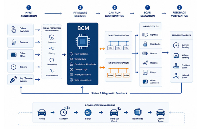
A driver action, sensor change or network message starts the control cycle.
The BCM validates the signal and applies firmware conditions before responding.
A local driver or networked module converts the decision into physical action.
Feedback confirms the result or identifies an abnormal operating condition.
The Three Ways a BCM Control Request Travels
It is easy to describe a body control module as a controller that receives an input and switches a load. In practice, however, the request can travel through three different paths. Understanding which path your vehicle uses helps you identify where the decision is made, where the electrical action occurs and where the final operating status comes from.
The BCM may respond to a local switch input, receive a request from another ECU through CAN communication, or coordinate a remote door, lighting or comfort module over LIN or CAN. In every case, the important question is not only who receives the request, but also who actually powers the physical load.
Local Input to Direct Load
In the most direct path, a local switch is connected to the BCM. The input circuit converts the electrical state into a software signal, the firmware decides whether the request is valid, and an onboard output stage controls the load.
A simple interior-light request is a useful example. You operate the switch, the BCM validates the input, and a local high-side switch, low-side switch or relay driver supplies the electrical path needed by the lamp.
Network Request to Direct Load
In this path, the original request does not come from a switch wired directly to the BCM. Another ECU or a central gateway sends a CAN message containing a function request or vehicle-state update.
The BCM still makes the final local decision and operates its onboard output stage. A welcome-light request is a typical example: the gateway reports an authorized unlock event, the BCM checks the current state, and its local driver activates the lighting load.
Input to Networked Module
The BCM does not directly power every body load. In a distributed system, it receives or generates a request, applies the central vehicle logic, and then sends a LIN or CAN command to a remote module.
The remote door, lighting or comfort module provides the local power stage. For example, the BCM can coordinate a window movement while the door module controls the motor and reports the final status back over the network.
Comparing the Three BCM Control Paths
| Control path | Decision location | Execution location | Feedback source |
|---|---|---|---|
| Direct local control | BCM | BCM output stage | Driver or load feedback |
| Network request, local execution | BCM | BCM output stage | Driver status |
| Distributed module control | BCM coordinates | Remote module | LIN/CAN status response |
A Local or Network Event Activates the BCM
Every BCM control cycle begins with an event. That event may come from you operating a switch, a sensor detecting a change, another ECU transmitting a message, a timer expiring or the vehicle moving between ignition and power states.
The BCM can respond differently depending on whether it is already active or is waiting in a low-power state. When active, it can immediately acquire the signal and begin validation. During BCM sleep mode, only selected wake-up paths remain available so that the vehicle can respond without keeping the entire controller fully powered.
Active-State Events
When the BCM is already active, a switch change, sensor update or network message can enter the normal control loop immediately. The controller still validates the signal, but it does not need to restore clocks, communication paths or processing resources first.
Sleep-State Wake-Up Events
When the vehicle is parked, the BCM may switch off nonessential circuits while keeping selected local inputs, bus activity detectors or timer functions alive. A valid BCM wake-up signal restores normal operation so the controller can examine the request.
Wake-Up Does Not Mean Immediate Execution
Bus activity or a changing switch level only tells the system that something may require attention. The BCM must restore processing and communication, confirm that the event is genuine, read the current vehicle state and then decide whether the requested action is allowed.
The BCM Acquires Input Signals
The BCM does not receive every input in the same electrical form. Some signals are simple on-or-off states, some represent changing analogue values, and others arrive as structured data messages from another vehicle module.
To understand BCM inputs and outputs, it helps to separate the physical signal present on a harness or communication bus from the validated software value that the firmware eventually uses.
Discrete Inputs
A discrete input represents a limited set of states, such as a switch being open or closed, a door being ajar or latched, or a lock request being active or inactive. After filtering and validation, the electrical level becomes a stable logical state that the firmware can use.
Analogue or Resistor-Coded Inputs
An analogue input represents a changing level, such as temperature, position or ambient-light intensity. A resistor-coded input can use several voltage ranges to represent multiple switch positions through one signal line. The front end converts these values into digital information before the software interprets them.
Network Inputs
A network input is already packaged as a CAN or LIN message. It may contain a function request, vehicle state, security permission, module status or diagnostic condition. The communication interface receives the frame, but the firmware still needs to determine whether the message is current, valid and relevant to the requested function.
Input Protection and Signal Conditioning
A signal coming from the vehicle harness cannot normally be treated as a clean MCU input. Long wiring paths, mechanical contacts, switching loads and electrical disturbances can change the voltage, introduce noise or generate rapid transitions that do not represent a real user request.
Before the firmware makes a decision, the front end must turn the raw electrical condition into a stable and believable BCM input signal.
Protection
Protection components reduce the chance that ESD, voltage transients, wiring faults or an incorrect external voltage will reach sensitive internal circuits.
Filtering
Filtering reduces short noise pulses and high-frequency interference caused by motors, PWM loads, relays or other switching activity elsewhere in the vehicle.
Debouncing
A mechanical switch may open and close several times during one physical press. Debouncing prevents the BCM from interpreting those rapid transitions as several separate commands.
Level and ADC Conversion
Voltage-level conversion adapts a harness signal to an internal logic level. Analogue-to-digital conversion turns a changing voltage into a numerical value that the software can compare with expected operating ranges.
The BCM Microcontroller Applies Vehicle Logic
The microcontroller does more than check whether an input is high or low. It interprets the request within the current vehicle condition, applies timing rules, checks permissions and determines whether another request or fault should block the action.
This is the central part of the BCM working principle. The same physical input can produce a different result depending on the ignition state, vehicle speed, security status, existing function state and other messages available to the controller.
Signal Validation
The MCU checks whether the signal is stable, has remained active long enough, agrees with related signals and comes from an expected network source.
Vehicle-State Context
The decision can depend on whether the ignition is on, the vehicle is moving, the doors are locked, the current power mode permits the function or the requested output is already active.
Permissions and Interlocks
Some actions are allowed only when several conditions are true. The request may need valid authorization, a safe vehicle state and the absence of a blocking fault before the firmware permits execution.
Valid request AND correct vehicle state AND required permission AND no blocking fault = command allowed
Timing Logic
BCM functions may distinguish between a short press and a long press, delay an output, stop an action after a timeout or automatically deactivate a load after a programmed period.
Priority and Conflict Resolution
When two requests conflict, the controller must determine which has higher priority, which result is safer and whether an active command should be completed, cancelled or delayed.
The BCM Exchanges Information with Other ECUs
Network communication does not occupy only one position in the control sequence. A message can arrive before the BCM makes a decision, and another message can leave after the decision has been made.
This is why BCM communication with other ECUs must be viewed as a two-way coordination process rather than a simple output channel.
Network Messages as Inputs
Other ECUs can provide vehicle state, a requested function, security authorization, system availability or fault information. The BCM combines these network values with local inputs before deciding what to do.
Network Messages as Outputs
After making a decision, the BCM can send a control command, state update, completion status, fault report or coordination request to another controller.
CAN in the BCM Control Flow
CAN commonly carries requests and vehicle-state information between the BCM, central gateway and other major ECUs. It allows the BCM to participate in functions that depend on information from several vehicle domains.
LIN in the BCM Control Flow
LIN is often used between the BCM and local door, mirror, seat or comfort nodes. The remote module handles local inputs and loads, while the BCM maintains the broader vehicle-level coordination.
The BCM Converts a Decision into Physical Action
A firmware decision is only a low-power logic result. It cannot directly provide the current required by most lamps, motors, relays or solenoids. The BCM therefore needs a power stage or a remote module that converts the command into an electrical action.
MCU command = low-power logic decision | Power driver = electrical control of the load
Depending on the selected control path, the command may reach a relay driver, smart high-side switch, low-side switch, motor driver or remote local module.
Direct Load Execution
An output stage located on the BCM PCB switches the battery or ground path for the load. The command can be a simple on/off state, a timed activation or a PWM control request.
Remote Load Execution
The BCM sends a network command, but the remote door, lighting or comfort module provides the actual power stage. The remote node can then return the operating status through LIN or CAN.
The BCM Verifies That the Command Was Completed
The BCM control cycle does not end when the command is transmitted. The controller must compare the requested state with the actual result so it can confirm correct operation or recognize that the load, wiring or remote module did not respond as expected.
This feedback stage is one of the most important differences between a simple switch and a modern body control module operation. The BCM can use electrical, mechanical or network information to close the control loop.
Driver Status
A smart output driver can report whether the output is active, whether a protection function has been triggered or whether an internal fault condition is present.
Current Feedback
Current information helps the BCM determine whether the load is drawing an expected amount of power, drawing no current or consuming more current than the operating state should require.
Voltage Feedback
Output voltage can show whether a load node reached the expected electrical state after the BCM enabled or disabled the driver.
Position or Status Input
A position switch, latch sensor or actuator status signal can confirm that the physical mechanism reached the requested final state.
Network Response
A remote module can report that a command was accepted, that the action is in progress, that the requested state has been reached or that a fault prevented completion.
Commanded State vs Observed State
| Commanded state | Observed state | BCM interpretation |
|---|---|---|
| Output ON | Expected feedback present | Operation completed |
| Output ON | No feedback | Open load or no response |
| Output OFF | Unexpected current or voltage | Wiring or driver abnormality |
| Network command sent | No module response | Communication or node issue |
Closing the BCM Control Loop
A control request is not complete simply because the BCM has activated an output. You still need a way to compare the requested state with the actual electrical, mechanical or network result.
This comparison allows the controller to distinguish a successfully completed action from a stalled actuator, missing module response or abnormal output condition. It is the final verification stage of the BCM control cycle.
Commanded State vs Observed State
| Commanded state | Observed state | BCM interpretation |
|---|---|---|
| Output ON | Expected feedback present | Operation completed |
| Output ON | No feedback | Open load or no response |
| Output OFF | Unexpected current or voltage | Wiring or driver abnormality |
| Network command sent | No module response | Communication or node issue |
| Movement requested | Position unchanged | Stall, blockage or timeout |
A BCM control cycle is not complete when the command is sent. It is complete when the resulting state has been verified or an abnormal condition has been identified.
Fault Handling and Vehicle Status Updates
When the observed result does not match the command, the BCM does not always declare a permanent fault immediately. A short disturbance, delayed actuator response or temporary network interruption may disappear before further action is required.
The controller first validates the abnormal condition. It may wait, retry the request, limit the output or temporarily disable the affected channel. If the condition persists, the BCM updates its internal status, stores diagnostic information and reports the condition through the vehicle communication network.
Validate Before Declaring a Fault
The BCM may check whether the abnormal feedback remains present, whether related signals support the same conclusion and whether the condition occurred during a valid operating window.
Retry, Limit or Disable the Action
Depending on the function, the BCM can retry the command, reduce the operating period, stop the output or prevent further activation until the vehicle state changes.
Protect the Harness and Load
An output may be switched off when continued operation could overheat the driver, damage the wiring or place unnecessary stress on the connected actuator.
Report the Updated Vehicle Status
Confirmed fault information can be sent to a gateway, instrument cluster or diagnostic system so the rest of the vehicle receives a consistent view of the affected function.
The BCM Enters Standby and Wakes Again
The BCM must remain ready to respond even when the ignition is off, but it cannot keep every circuit fully active while the vehicle is parked. It therefore moves between active, post-operation, standby and wake-up states.
This state management allows the vehicle to react to a keyless-entry request, door switch, timer or network event while reducing unnecessary battery consumption during BCM sleep mode.
Active Mode
The microcontroller, required communication interfaces and relevant output channels are available for normal control activity.
Post-Operation State
After an action completes, the BCM updates its status, waits for related activity to finish and confirms that no pending command requires it to remain active.
Standby or Sleep
Nonessential functions are reduced or switched off while selected monitoring and wake-up paths remain available.
Wake-Up Detection
A valid wake-up source may include:
Reinitialization
After wake-up, the BCM restores MCU execution, network communication, input reading and the current vehicle-state context before processing any pending request.
How a BCM Unlocks a Car Door
A remote door-unlock request provides a clear example of how the complete BCM control flow works. The request begins outside the BCM, moves through security and vehicle-state checks, reaches either a local driver or remote door module, and ends only after the lock status has been verified.
Following this one sequence helps you see how BCM input processing, CAN and LIN communication, firmware decisions, load execution and feedback verification operate as one connected system.
Door-Unlock Control Sequence
You press the unlock button on the key fob.
The keyless-entry receiver or gateway recognizes and validates the request.
An authorized unlock message is transmitted to the BCM through the vehicle network.
If necessary, the BCM wakes from standby and restores its processing and communication functions.
The MCU validates the message and checks the current lock, security and vehicle-power states.
Firmware confirms that the required permission is present and no condition blocks the unlock command.
The BCM either activates a local lock driver or sends a LIN command to the door module.
The output stage or door module provides current to the lock actuator.
Lock position, driver current or module-status feedback returns to the BCM.
The BCM confirms whether the requested unlock action was completed.
The BCM updates the vehicle door and lock status.
Related functions such as welcome lighting may be coordinated.
After activity ends, the system returns to a low-power state.
How Automatic Headlight Control Flows Through the BCM
The ambient-light sensor produces a changing signal. After filtering and conversion, the BCM compares the light level with the ignition state, driver settings and current lighting state. If the programmed conditions are satisfied, it sends a lighting command to an onboard driver or a separate lighting module. Lamp or driver feedback then confirms whether the requested lighting state was reached.
BCM Inputs, Decisions, Outputs and Feedback
You can use the following summary to trace any body-control function from the first input event to the final power state.
| Control stage | Typical information | BCM responsibility |
|---|---|---|
| Input | Switch, sensor or network message | Acquire and validate |
| Context | Vehicle state, permission and timing | Determine whether action is allowed |
| Decision | Firmware control result | Select direct or networked execution |
| Output | Driver command or bus message | Initiate physical action |
| Feedback | Current, voltage, position or node status | Confirm actual result |
| Fault handling | Unexpected or missing feedback | Protect, record and report |
| Power state | Activity or wake-up condition | Remain active or enter sleep |
What Engineers Must Define for a Complete BCM Control Flow
When you review a new body-control function, the following questions help you define the full signal path before selecting individual components.
What event starts the control sequence?
Is the input local, analogue or network-based?
What conditions must be true before execution?
Is the load controlled directly or through another ECU?
What feedback proves that the action succeeded?
How long should the BCM wait before declaring a timeout?
What happens after abnormal feedback?
Which state and fault information must be sent over the network?
What sources are allowed to wake the BCM?
When may the module safely return to sleep?
Explore the Complete BCM Architecture and IC Categories
Once you have defined the complete signal and control flow, you can map each stage to the required input interfaces, MCU resources, CAN or LIN communication, power drivers, supervision circuits and diagnostic functions.
Body Control Module Architecture, Design Rules and IC SelectionFAQs – Body Control Module Working Principle
These answers help you understand how a body control module works, from receiving input signals and applying firmware logic to controlling loads, verifying feedback and managing sleep or wake-up states.
How does a BCM module work? +
A BCM module works by receiving signals from switches, sensors and other ECUs. Its input circuits protect and convert those signals before the microcontroller applies programmed vehicle logic. The BCM then activates an onboard driver or sends a CAN or LIN command to another module. Feedback allows it to verify the result, update vehicle status and identify abnormal conditions.
What types of input signals does a BCM receive? +
A BCM typically receives discrete switch states, analogue or resistor-coded values and network messages. These can represent a door switch, ambient-light level, actuator position, security authorization or another ECU’s status. Each raw BCM input signal must be protected, converted and validated before firmware treats it as a reliable software value.
What happens after the BCM receives a command? +
After receiving a command, the BCM validates the signal and checks conditions such as ignition state, vehicle speed, security permission, timing and existing faults. If the request is allowed, the firmware selects either direct load control or networked execution. The BCM then waits for current, voltage, position or module-status feedback before marking the action complete.
Does a BCM directly power every vehicle load? +
No. Some loads are controlled directly through relay drivers or smart high-side and low-side switches located inside the BCM. Other functions use a distributed design in which the BCM sends a LIN or CAN control message to a door, lighting or comfort module. That remote module then provides the electrical power required by the local load.
How does a BCM communicate with other ECUs? +
The BCM communicates with other ECUs through vehicle networks such as CAN and LIN. It can receive function requests, security authorization, power-mode information and module status. It can also transmit control commands, fault information and updated body-system states. This two-way BCM network communication allows several controllers to coordinate one vehicle function.
What is the role of CAN and LIN in BCM operation? +
CAN commonly connects the BCM with gateways and other major vehicle ECUs, carrying broader vehicle-state information and function requests. LIN is often used for local door, mirror, seat and comfort nodes. In both cases, the network can provide an input to the BCM or carry an output command after the BCM firmware decision.
How does a BCM control a relay, lamp or motor? +
The MCU produces a low-power logic command that is passed to a relay driver, smart power switch, motor driver or remote control module. That power stage connects the load to the required battery or ground path. Depending on the function, the output can be on/off, timed, PWM-controlled or directional. The BCM then checks load feedback.
How does the BCM know whether a load responded correctly? +
The BCM compares the requested state with current, voltage, position, driver-status or network feedback. Expected feedback confirms that the action completed. Missing current may indicate an open load, unchanged position may indicate a stalled actuator, and a missing network response may indicate an unavailable module. This feedback verification closes the control loop.
What happens when BCM feedback does not match the command? +
The BCM first validates whether the mismatch is temporary or persistent. It may wait, retry the command, limit the output or disable the channel to protect the load and wiring. If the abnormal condition continues, the controller updates its internal status, stores diagnostic information and reports the BCM fault status over the vehicle network.
Why does a BCM enter sleep mode? +
A BCM enters sleep or standby mode to reduce battery consumption when the vehicle is parked and no active body-control function is required. Nonessential circuits are reduced or switched off, while selected monitoring and wake-up paths remain available. This allows BCM power-state management to balance low power consumption with continued responsiveness.
What can wake a BCM when the vehicle is parked? +
A BCM can be awakened by an approved local switch, keyless-entry event, LIN or CAN bus activity, timer, ignition change or vehicle power-state transition. After detecting a valid BCM wake-up event, the controller restores MCU execution, communication and input monitoring before validating and processing the request.
Does the BCM continue working when the ignition is off? +
Yes, but usually not at full operating power. After the ignition is switched off, the BCM may complete pending actions, update vehicle status and then enter a low-power state. Selected circuits remain able to monitor door, keyless-entry, timer or network events so the body control module can wake when the vehicle needs it.