
Why DDR5 Server Memory Reliability Depends on Power Integrity
If your server works at idle but becomes unstable under a memory-intensive workload, the DRAM may not be the only place to look. DDR5 reliability begins with the power path that supplies, sequences and supervises the DIMM before the first data transaction occurs.
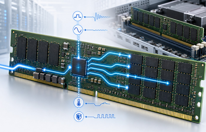
DDR5 Reliability Begins Before Data Is Transferred
Modern servers depend on DDR5 bandwidth and capacity to keep AI workloads, virtual machines, databases and high-performance computing systems supplied with data. But higher performance only becomes useful when every memory module can operate predictably through startup, traffic bursts, temperature changes and recovery events.
When you investigate an intermittent DDR5 problem, the visible symptom may appear in memory training, an ECC log or a system restart. The underlying condition, however, may have developed earlier in the DIMM power path.
Does your server pass idle testing but fail under heavy memory traffic?
Does the same DIMM fail during a cold boot but recover after restarting?
Do memory errors increase as the module temperature rises?
Do the rails appear normal only after the server has already recovered?
None of these symptoms proves that the PMIC is at fault. They do show why stopping at the DRAM chips, memory-training results or ECC records can leave an important part of the evidence unexplored.
Before data can be read or written, the server platform must deliver input power to the DIMM. The module must then convert that input into multiple local rails, bring those rails up in the correct sequence, monitor their operating conditions and respond predictably when a limit is exceeded. A weakness in transient response, ripple control, ramp timing, thermal behavior or protection recovery may eventually appear as a memory failure somewhere else in the system.
DDR5 power integrity is not simply about holding a rail at its nominal voltage. It includes transient response, sequencing, ripple control, thermal behavior, protection states and the ability to preserve fault evidence.
Why DDR5 Raises the Importance of Power Integrity
When you move from DDR4 to DDR5, you are not only increasing memory bandwidth. You are also changing the conditions under which the memory power domain must remain stable. DDR5 VDD and VDDQ typically operate at 1.1V, compared with the typical 1.2V used by DDR4, while modern server DIMMs support greater capacity, higher transfer rates and sustained data-intensive workloads.
This does not mean that DDR5 is inherently unreliable. It means that your validation must account for both the nominal voltage and the dynamic behavior of each rail. Higher-speed operation places tighter demands on timing and system margin, while changes in memory activity can create fast, workload-dependent current transitions that the PMIC and DIMM power-delivery network must support.
If you only check the average voltage, an unstable rail may still appear normal. A meter may report a value close to 1.1V even though the rail briefly experiences transient droop, overshoot, switching ripple or recovery ringing during a burst of memory activity.
Shows whether a sudden load increase pulls the rail below its permitted operating window.
Reveals overshoot that may occur during startup or when a heavy load is suddenly released.
Helps you identify switching-mode changes, PDN weakness and insufficient damping.
Shows how quickly the rail returns to a stable condition after a workload transition.
| Dimension | DDR4 | DDR5 | Reliability Implication |
|---|---|---|---|
| Core/I/O voltage | Typically 1.2V | Typically 1.1V | Less absolute headroom for rail excursions |
| Power conversion | Primarily motherboard-side | Moved onto the DIMM | The module becomes a local power domain |
| Load behavior | Lower bandwidth generation | Higher bandwidth and density | Faster and more complex load transitions |
| Observability | Limited module-level power evidence | PMIC status, telemetry and alerts | Better fault localization when evidence is logged correctly |
The practical conclusion is not that a digital 0 and 1 are simply “closer together.” It is that you must keep each supply rail inside its permitted operating window while also protecting the timing and signal margins required by higher-speed DDR5 operation.
How On-DIMM Power Regulation Changes the Architecture
With DDR4, the motherboard primarily generates the low-voltage memory rails and distributes them to the DIMM. DDR5 changes that boundary. Your server platform provides an input supply to the module, and the local PMIC converts that input into the rails required by the DRAM and module-management devices.
In a server DIMM, the DDR5 PMIC (on-DIMM) acts as the local control point for multi-rail conversion, sequencing, telemetry and fault response, making it central to both memory stability and power-side diagnosis.
Moving conversion closer to the DRAM shortens the low-voltage distribution path and gives you greater module-level control and visibility. It also concentrates power conversion, startup timing, thermal behavior and protection decisions within the limited physical area of the DIMM.
Most conversion and power supervision remain on the motherboard side.
Conversion, sequencing, monitoring and fault response move into the DIMM power domain.
| Rail | Primary Role | Reliability Concern |
|---|---|---|
| VDD | DRAM core power | Sustained load, voltage droop and thermal coupling |
| VDDQ | DRAM I/O power | Fast transients, ripple and activity-dependent instability |
| VPP | Wordline and pump-related domain | Ramp behavior, undervoltage and sequencing |
| VDDSPD | SPD and management domain | Telemetry access and management continuity |
When you investigate a failure, the rail identity helps determine what evidence to examine first. A load-related VDDQ event, a VPP startup problem and a VDDSPD access loss may all appear as memory instability, but they point to different validation paths.
Power Integrity and Signal Integrity Are Different—but Coupled
When you see a closed data eye, increased jitter or an intermittent read error, it is important not to label every symptom as a PMIC problem. Power integrity describes the quality and behavior of the supply rails, while signal integrity describes how accurately data, strobe, clock and command signals travel between devices.
These are separate engineering domains, but they are not isolated. Power noise can reduce the operating margin of an I/O circuit, while routing, return paths and temperature can influence both rail behavior and signal quality.
Where Power and Signal Behavior Interact
May reduce the operating margin available to DDR5 I/O circuitry.
Can couple switching current into sensitive signal or measurement nodes.
May influence driver and receiver behavior during high-speed transactions.
Can alter both PMIC performance and the electrical behavior of the signal channel.
Power integrity does not replace signal-integrity analysis, and signal equalization cannot compensate for a collapsing power rail.
Four Complementary Reliability Mechanisms
You obtain the clearest diagnosis when each mechanism is used for the type of problem it was designed to address.
Helps address high-speed channel distortion and inter-symbol interference.
Helps detect certain transferred-data errors across supported paths.
Corrects defined internal DRAM errors before data leaves the device.
Helps you identify power-side events, rail conditions and protection states.
Four Power Conditions That Can Destabilize DDR5 Memory
A DDR5 rail can report the expected voltage during a steady-state check and still become unstable during startup, a rapid workload transition or a thermal event. To understand what your server is actually experiencing, you need to examine the power domain across time rather than relying on a single DC measurement.
The four conditions below do not automatically prove that the PMIC is the root cause. They provide practical power-side hypotheses that you can compare with rail waveforms, temperature data, fault states and the exact phase in which the failure occurs.
Transient Droop and Overshoot
Memory activity is not a constant load. When your server moves from an idle condition to a burst of reads, writes or memory training activity, current demand can change much faster than a conventional DC measurement can reveal. The PMIC control loop and the DIMM power-delivery network must supply the additional energy while keeping the affected rail inside its permitted window.
If the response is too slow or the available local energy is insufficient, the rail may experience a brief voltage droop. When the workload suddenly decreases, the stored energy and control-loop response may instead produce overshoot or recovery ringing. These short events can explain a workload-related failure even when the average rail voltage appears correct.
Ripple, Decoupling and PDN Behavior
The PMIC generates DDR5 rails through switching conversion, so some periodic ripple is expected. What matters is whether the waveform remains within the required limits across startup, idle operation, sustained activity and rapid load changes.
At light load, a converter may enter PFM, pulse-skipping or another efficiency-oriented operating mode. The resulting waveform can look very different from the steady switching pattern observed at heavier load. A change in waveform shape is not automatically a fault, but it should be correlated with warnings, memory activity and any increase in error frequency.
Determines stored charge, but it does not fully describe high-frequency behavior.
Influence damping, impedance and how effectively a capacitor responds to fast current changes.
Determine the real current-loop area and the parasitic impedance seen by the load.
Two DIMM designs can use the same total capacitance and still produce different transient and ripple results. Package size, capacitor location, via count, copper geometry and the return path all affect the actual impedance between the PMIC and the DRAM load.
Placement and return-path quality can matter as much as nominal capacitance.
Sequencing, Ramp and Pre-Bias
VDD, VDDQ, VPP and the module-management supply cannot be validated only after they reach their final values. The order in which the rails rise, their ramp slopes and the relationship between them during startup can all affect whether the DIMM enters a stable operating state.
The PMIC’s PG/READY decision window must reflect the real rail behavior. If blanking, deglitch timing or ramp limits do not align with the physical startup waveform, a rail may be interpreted as invalid even though its final steady-state voltage eventually looks correct.
A fast restart can create a different starting condition from a full cold boot. Residual voltage may remain on one or more rails, creating pre-bias. If the PMIC, discharge path or load does not handle that condition predictably, reverse-current paths and altered ramp measurements can make cold, warm and rapid-restart behavior inconsistent.
A brownout can also place the PMIC into a fault-action or retry state. If the state is cleared by a complete power removal, the issue may appear to have disappeared even though the original trigger was never identified.
Thermal Derating and Protection Response
The PMIC shares a compact module with multiple DRAM packages, so PMIC self-heating and nearby DRAM activity can create a combined thermal load. Server airflow direction, heatsink coverage, slot position and neighboring modules can all change the local temperature experienced by the DIMM.
The PMIC’s internal temperature sensor may respond quickly to local silicon heating, while an external board sensor may report a slower and lower value. If you compare only one measurement point, you may miss the difference between the measured temperature and the actual local hotspot.
Evidence You Should Correlate
How Protection May Appear
A higher temperature does not prove that the PMIC caused the failure. Confirm the relationship between load, current, temperature, airflow and the recorded PMIC state before assigning a root cause.
Why Power Problems Often Look Like Memory Problems
Your first visible symptom may be a failed memory-training sequence, an ECC event, an ALERT# transition or an unexpected server reset. That symptom tells you where the system noticed the problem—not necessarily where the problem began.
Use the following relationships as investigation paths. Each power-side mechanism is a possible explanation that must be confirmed with captured evidence.
| Observed Symptom | Possible Power-Side Mechanism | Evidence to Check First |
|---|---|---|
| Cold-boot initialization failure | Ramp window or pre-bias issue | Power-up waveform, PG state and first fault snapshot |
| Stable at idle, errors under load | VDDQ transient or DIMM PDN weakness | Rail minimum, ripple shape and fault timing |
| Errors increase with temperature | Thermal derating or reduced transient margin | PMIC temperature, current and derating flags |
| Server resets during activity bursts | UV/OCP action or coupled rail collapse | Fault type, rail identity and collapse order |
| ALERT# repeatedly toggles | Threshold edge, mode transition or warning chatter | Warning bits, event frequency and operating point |
| PMIC status becomes unreadable | Management rail or bus-access issue | VDDSPD, bus timeouts and retry results |
| Failure disappears after a reboot | Hiccup recovery or loss of fault evidence | Latched state captured before reset |
Treat every row as a hypothesis, not a diagnosis. Confirm the mechanism by matching the symptom to rail identity, event timing, measured conditions and PMIC state.
What On-Die ECC Can—and Cannot—Protect
DDR5 On-Die ECC improves reliability inside the DRAM device. It checks protected internal data and corrects defined errors before the data is presented outside the DRAM. This helps manage internal error mechanisms as DRAM density continues to increase.
However, On-Die ECC does not provide complete protection for every stage between the memory controller and the DIMM. It cannot tell you why a PMIC entered a protection state, why a rail collapsed during startup or why module-level telemetry became unavailable.
What On-Die ECC Supports
What It Does Not Replace
On-Die ECC strengthens reliability inside the DRAM device, but it does not replace stable power delivery, module-level fault evidence or system-level ECC protection.
Even when an internal single-bit error is corrected, you still need enough context to determine whether the event was isolated or part of a wider power, thermal or workload-related pattern. That means comparing memory-error information with PMIC telemetry and protection states.
Questions to Ask After an ECC Event
Use the following evidence to decide whether the event should remain classified as an internal memory correction or trigger a broader power-side investigation.
Did the error occur near a warning, ALERT# event or state transition?
Was a UV, OC or OT condition recorded at the same time?
Does the event repeat only at a specific temperature or workload?
Is the system-level correctable-error count increasing over time or under repeatable conditions?
Telemetry Turns Intermittent Failures into Evidence
An intermittent DDR5 failure becomes difficult to diagnose when you only see the system after it has recovered. A rail may have briefly crossed a limit, the PMIC may have entered a protection state, and an automatic retry may already have restored normal operation before you begin reading its status.
Useful telemetry is therefore more than a collection of voltage values. You need to combine continuous measurements, event evidence and historical access information to understand what happened, when it happened and whether the PMIC had already started recovering.
Continuous Telemetry
Trend and operating-state evidenceUse continuous values to identify sustained droop, thermal rise and workload-related trends. Because telemetry is sampled and filtered, it may not capture a very short transient.
Event Evidence
Trigger and protection evidenceUse event evidence to determine what crossed a threshold and how the PMIC responded. A latched event can preserve information after a short electrical condition has disappeared.
History and Access Evidence
Intermittency and visibility evidenceUse history and bus-health information to distinguish a real absence of faults from a situation in which the host could not read the evidence.
Minimum Fault Snapshot
| Field | Diagnostic Value |
|---|---|
| Timestamp | Connects the event to a boot, workload or temperature phase |
| Rail | Identifies the affected power domain |
| Fault type | Separates UV, OV, OC, OT and short-circuit responses |
| Voltage / current / temperature | Quantifies the operating condition close to the event |
| PMIC state | Shows whether the PMIC was normal, ramping, retrying, latched or recovering |
| Bus health | Explains missing, delayed or incomplete evidence |
A server restart may clear fault bits, latched states and the exact protection condition that triggered the event. A normal voltage reading after recovery does not prove that the rail remained normal when the failure occurred.
How to Validate DDR5 Power Integrity
A DIMM that powers up successfully has passed only the first validation condition. To demonstrate reliable operation, you need to verify its rails across startup, workload transitions, temperature changes, intentional fault conditions and repeated recovery cycles.
The following workflow moves from static checks to dynamic and fault-oriented testing. Each stage should leave you with measurable evidence rather than a simple “pass” observation.
Static Rail Verification
Confirm that the basic configuration is coherent, but remember that static correctness is only the starting point.
Power-Up and Power-Down Timing
Ripple and Load-Step Testing
Thermal Validation
Protection and Recovery Testing
Telemetry and Bus Robustness
Measurement Matters
Your measurement path can create or hide the apparent problem.What Engineers Should Check When Selecting a DDR5 PMIC
A PMIC can meet its nominal output-voltage and current specifications while still creating difficult integration or field-debug conditions. Before you approve a device for a DDR5 DIMM, evaluate how it behaves during startup, fast load changes, thermal stress and fault recovery—not only under steady-state laboratory conditions.
The most useful supplier response is not a list of features. It is a clear description of what the PMIC does before, during and after an abnormal condition, and what evidence remains available to you.
Architecture and Current Capability
Does the PMIC support your required DIMM class and rail topology?
What are the continuous and peak current capabilities for each rail?
How does current limiting behave during startup and a fast workload burst?
Sequencing and Protection
How are ramp order, slope and timing windows configured?
How does the PMIC handle pre-biased rails?
What happens after UV, OC or OT detection, and what clears the fault?
Telemetry and Bus Access
Which voltage, current and temperature values can you read?
How quickly is telemetry updated, and are fault states latched before retry?
How does ALERT# assert, persist and clear?
Can bus access recover reliably during noise, timeouts or fault conditions?
Thermal and Production Control
What light-load switching modes are used, and how do they affect ripple?
Which thermal, copper, heatsink and airflow assumptions support the ratings?
How are configuration versions locked, verified and traced through production?
Before selecting a PMIC, ask the supplier for a complete fault narrative: what triggers each protection mode, what action follows, what evidence is latched, how recovery occurs and what the host can still read before the state is cleared.
From DIMM Stability to Data Center Uptime
A short DDR5 rail disturbance may last only microseconds or milliseconds, but its operational effects can continue much longer. If the event interrupts initialization, triggers a protection response or reduces the margin available during heavy memory traffic, the system may respond with a training retry, an error report or a complete restart.
At data center scale, you are not evaluating one isolated DIMM. You are managing repeated workloads, multiple memory channels, large server fleets and production lots that must behave consistently. A power condition that appears minor on one module can become a serviceability problem when it repeats across systems.
How a Short Power Event Can Affect Operations
Startup takes longer or becomes inconsistent across cold, warm and rapid-restart conditions.
A protection action or coupled rail collapse may interrupt an active workload.
Repeated events can indicate a developing workload, thermal or module-level margin problem.
Your team may need to remove a server from service before the failure mechanism is understood.
A DIMM may be replaced because it appears faulty even though the original evidence was cleared during recovery.
A common configuration, thermal or PDN weakness may reproduce across multiple modules.
Missing fault evidence forces your team to reproduce a condition that may be rare and workload-dependent.
At the platform level, the broader Data Center & Servers design context connects DIMM power behavior with processor loading, thermal management, system monitoring and long-term serviceability.
Recovery Alone Is Not Enough
A module returning to normal operation is useful, but it does not complete the investigation. For reliable fleet operation, you need enough evidence to answer four additional questions.
Identify the rail, fault type, operating state and system phase involved.
Repeat the relevant startup, workload, airflow or temperature condition.
Use consistent snapshots to compare modules, slots, servers and production lots.
Detect abnormal temperature, warning or bus behavior before deployment.
Final Takeaway: Reliable DDR5 Requires Stable Power and Preserved Evidence
DDR5’s 1.1V VDD and VDDQ rails are only part of the reliability challenge. Predictable operation depends on multiple rails working together through startup sequencing, fast load transitions, PDN behavior, thermal stress and protection recovery.
On-Die ECC, CRC and signal equalization strengthen different parts of the DDR5 reliability chain, but they cannot replace a stable module-level power domain. They also cannot explain why a rail crossed a limit or why the PMIC entered hiccup, latch-off or thermal derating. For that, you need preserved fault evidence tied to the workload and operating condition.
When you validate power behavior dynamically and retain the first fault snapshot, an intermittent memory problem becomes easier to reproduce, compare and resolve. That reduces unnecessary module replacement and helps you carry reliable behavior from a single DIMM into production systems and data center fleets.
The most reliable DDR5 platform is not simply the one that powers up successfully. It is the one whose power behavior can be validated, monitored and explained under real workloads.
Frequently Asked Questions About DDR5 Power Integrity
These answers help you distinguish module-level power behavior from DRAM, signal-channel and system-level reliability mechanisms when diagnosing DDR5 server memory.
Why does DDR5 use 1.1V?
DDR5 typically reduces VDD and VDDQ from the 1.2V commonly used by DDR4 to 1.1V to improve energy efficiency as memory bandwidth and capacity increase. Lower nominal voltage does not automatically mean that every DDR5 module consumes less total power, because actual consumption also depends on density, activity and module configuration. The local rails must still remain inside their permitted voltage, ripple and transient windows during startup and changing workloads.
Why is the PMIC placed on a DDR5 DIMM?
Placing the PMIC on the DDR5 DIMM moves key voltage conversion closer to the DRAM loads. The PMIC receives a platform-supplied input and generates the local rails required by the module. This shortens the low-voltage distribution path and enables module-level sequencing, protection, monitoring and fault reporting. It also means that conversion losses, thermal behavior and protection states must now be evaluated within the physical environment of the DIMM.
Can poor power integrity cause memory training failures?
Yes, poor power integrity can contribute to memory training failures, but a failed training sequence does not prove that the PMIC is responsible. Incorrect rail order, unsuitable ramp timing, pre-bias, transient droop or an unexpected protection action can prevent the DIMM from reaching a stable initialization condition. Confirm the relationship by capturing the power-up waveforms, PG/READY behavior, PMIC state and first fault snapshot during the failed attempt.
What is the difference between DDR5 power integrity and signal integrity?
Power integrity describes the accuracy and dynamic behavior of the DDR5 supply rails, including ripple, transient droop, overshoot, decoupling, sequencing and return paths. Signal integrity describes the quality of DQ, DQS, command, address and clock signals, including eye opening, timing margin, reflections, crosstalk and inter-symbol interference. The two domains are different but coupled because supply noise, shared return paths and temperature can influence I/O timing and waveform margin.
Can DDR5 On-Die ECC correct power-related errors?
DDR5 On-Die ECC corrects defined errors inside the DRAM device before data is presented outside the chip. It does not replace stable power delivery, system-level ECC or channel-level protection. It also cannot diagnose PMIC sequencing problems, rail collapse, bus-access loss or a protection state. If an ECC event appears near a voltage, temperature or workload anomaly, compare it with PMIC warnings and fault telemetry before assigning a root cause.
Why does DDR5 memory work at idle but fail under load?
A DIMM may pass idle testing because its current demand and thermal load remain relatively low. Under heavy memory traffic, fast load transitions can expose VDD or VDDQ droop, insufficient decoupling, rail-to-rail coupling, PMIC mode transitions or reduced thermal margin. The average DC voltage may still look correct. Capture the rail minimum, overshoot, ripple shape, recovery time, PMIC state and module temperature during the workload that reproduces the failure.
What PMIC telemetry should be logged during a server fault?
Your minimum PMIC fault snapshot should include a timestamp, rail identity, warning and fault type, voltage, current, temperature, PMIC operating state and the ALERT# cause. Also record bus health, including failed reads, timeouts and retry results, because missing telemetry may indicate an access problem rather than the absence of a fault. Add the boot stage, workload phase and airflow or temperature condition so that the event can be reproduced and compared across servers.
How should engineers test DDR5 rail ripple and transient response?
Measure DDR5 rail ripple and transient response close to the relevant load with a short probe ground path and documented bandwidth and trigger settings. Compare light-load and heavy-load waveforms, then apply repeatable workload or load-step transitions to capture rail minimum, maximum, ringing and recovery time. Correlate each waveform with PMIC mode, temperature and fault status. Always distinguish genuine rail behavior from ringing or noise introduced by the probe loop.