
Smart High-Side and Low-Side Switches for BCM
Choose the right protected power switch for each BCM output instead of selecting a device by current rating alone.
Your BCM MCU GPIO cannot directly drive automotive lamps, heaters, relay coils, solenoids and other body loads. A smart high-side or low-side switch sits between the MCU and the load, providing controlled power switching together with current limiting, short-circuit protection, thermal shutdown and diagnostic feedback.
This guide helps you match the switch topology, current capability, protection features and diagnostic interface to your actual BCM load. It is not a general MOSFET introduction—it is a practical BCM load-driver IC selection guide.
Select your BCM power switch according to:
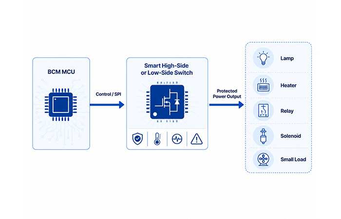
BCM Output Path
BCM MCU → Control / SPI → Smart High-Side or Low-Side Switch → Protected Power Output → Lamp · Heater · Relay · Solenoid · Small Load
What Do Smart Power Switches Do in a BCM?
Your BCM microcontroller can make control decisions, but its GPIO pins cannot directly supply the current required by lamps, heaters, relay coils, solenoids and other vehicle loads. An automotive smart power switch acts as the power-output stage between the MCU and the load.
When you select a body control module load driver, you are choosing more than an electronic on-off switch. The device must carry the normal load current, survive startup events and protect the wiring when an abnormal condition occurs.
Switch the Load Current
The switch connects or disconnects battery power according to the MCU control signal.
Handle Startup Current
It must tolerate lamp inrush, capacitor charging current and inductive-load startup pulses.
Protect the Output
Integrated protection can limit current or shut the channel down during short circuits, overloads or excessive temperature.
Return Diagnostic Feedback
Analog, digital or SPI feedback allows the MCU to identify current levels and output faults.
Keep the roles separate: the MCU supplies the logic command, while the BCM output driver carries the power. Depending on your channel count and diagnostic strategy, the output device may be single-channel, multi-channel or software-configurable. Protection features vary by device, so you should verify every required function in the datasheet.
| Device type | Integrated protection | Diagnostics | External components | Typical use |
|---|---|---|---|---|
| Discrete MOSFET | Limited | None | More | Cost-sensitive simple output |
| Protected MOSFET | Basic | Limited | Medium | Protected single load |
| Smart power switch | Extensive | Analog, digital or SPI | Lower | Protected BCM output |
| Mechanical relay | Mechanical isolation | Usually none | Driver required | Selected high-inrush loads |
High-Side vs Low-Side Switches in a BCM
The difference between a BCM high-side switch and a BCM low-side driver is the position of the switching device in the current path. That position determines how the load is referenced, which wiring faults matter most and how diagnostics should be implemented.
A high-side switch is placed between the positive battery rail and the load. A low-side switch is placed between the load and ground. Neither topology is automatically better; the correct choice depends on your actual load connection and fault model.
Typical High-Side Loads
Choose a high-side topology when the load is normally referenced to ground.
Lamps · Heaters · ECU power feeds · Ground-referenced body loads
Typical Low-Side Loads
Choose a low-side topology when the load is permanently connected to the positive supply.
Relay coils · Solenoids · Valves · Indicator LEDs · Selected small actuators
| Selection factor | High-side switch | Low-side switch |
|---|---|---|
| Switch location | Battery side | Ground side |
| Load reference | Ground | Battery positive |
| Common loads | Lamps, heaters, power feeds | Relays, solenoids, valves |
| Key wiring fault | Short to ground | Short to battery |
| Typical diagnostics | Open load, current sense, short circuit | Open load, clamp status, short circuit |
| Common interface | Direct input or SPI | Direct input, parallel control or SPI |
Do not choose the topology by habit alone.
Your decision should reflect the harness topology, fault model, grounding method, required diagnostic coverage and the turn-off behavior of any inductive load.
Match the Switch to the BCM Load Type
Two loads with the same nominal current can place very different stress on an automotive load driver. A heater may draw a relatively stable continuous current, while a cold lamp, relay coil or capacitor-input module can create a short but much higher current event.
Before choosing an automotive smart power switch, identify whether your load is resistive, lamp-based, inductive or capacitive. This determines which current profile, diagnostic behavior and protection feature matters most.
Resistive Loads
Typical examples include heaters, defogger elements and some incandescent loads.
Check continuous current, duty cycle, connector temperature and steady-state thermal dissipation.
Lamp Loads
Typical examples include halogen lamps, incandescent lamps and lighting power feeds.
Check cold-filament inrush, off-state leakage, open-load detection, PWM dimming and short-circuit protection.
Inductive Loads
Typical examples include relay coils, solenoids, valves and electromagnetic latches.
Check stored energy, flyback path, active-clamp capability, turn-off speed and repetitive pulse performance.
Capacitive Loads
Typical examples include LED modules, filtered power rails and capacitor-input electronics.
Check charging current, soft-start behavior, current-limit profile, retry timing and false short-circuit detection.
| Load type | Main electrical risk | Typical switch | Critical feature |
|---|---|---|---|
| Lamp | Cold inrush | High-side | Inrush tolerance, open-load detection |
| Heater | Continuous power | High-side | Low RDS(on), thermal capacity |
| Relay coil | Inductive kick | Low-side | Active clamp or flyback handling |
| Solenoid | Inductive energy | Low-side | Clamp energy, fast release |
| LED module | Leakage and diagnostics | High-side | Low leakage, configurable diagnosis |
| Capacitive input | Charging surge | High-side | Current limiting, soft start |
Smart High-Side Switches for BCM Outputs
You normally use a smart high-side switch for BCM channels where one side of the load is permanently connected to vehicle ground. The switch sits between the positive battery rail and the load, allowing your BCM to distribute power while keeping control, protection and diagnostic functions inside one automotive-qualified device.
Unlike a simple discrete MOSFET, an automotive high-side switch typically combines an N-channel power MOSFET, a charge pump, current-limiting circuitry, thermal protection and diagnostic feedback. This reduces the number of external components you need around each protected BCM output.
Your final choice should reflect the number of channels, load-current profile, thermal conditions and the amount of feedback your MCU requires. A simple single-channel output may only need a direct logic input, while a multi-channel automotive high-side switch may use SPI for configuration, channel control and detailed fault reporting.
Features You Should Verify
Typical BCM Applications
A BCM lamp driver IC may control interior or exterior lighting feeds, while other high-side channels can power heaters, selected small fans, electronic modules, pumps or actuator power feeds. You still need to verify the load’s continuous current, inrush current and switching behavior before assigning it to a particular output channel.
Keep the motor-control boundary clear.
A single high-side switch does not provide bidirectional control for a power-window or door-lock motor. These loads normally require an H-bridge or dedicated motor-driver stage. A high-side switch may still control the power feed, relay or auxiliary channel associated with the motor system.
Smart Low-Side Switches for Relays and Solenoids
You use an automotive low-side driver when the load is permanently connected to the positive battery supply and the switch completes the circuit to ground. This topology is widely used for relay coils, solenoids, valves, indicators and selected small automotive loads.
A smart low-side switch can combine the power transistor with current limiting, thermal shutdown, open-load detection and short-circuit feedback. One-channel devices suit independent or higher-priority loads, while two-channel devices can reduce PCB area when you need to control similar loads with comparable current levels.
For a relay coil low-side driver or solenoid low-side driver, the most important engineering question is not only the steady current. You must also determine how the magnetic energy will be released when the channel turns off.
Stored inductive energy
E = ½ × L × I²
Higher inductance or current increases the energy that the switch, clamp or external suppression network must safely absorb.
Safe Turn-Off Options
You can release inductive energy through a flyback diode, an internal active clamp, an external TVS or the verified avalanche capability of the switching device. The correct option depends on your acceptable clamp voltage, release time, pulse frequency and thermal margin.
| Turn-off method | Main benefit | Main trade-off | What you should verify |
|---|---|---|---|
| Flyback diode | Low switch stress | Slower current decay | Release time and diode current |
| Active clamp | Faster solenoid or relay release | Higher device dissipation | Clamp voltage and repetitive energy |
| External TVS | Controlled clamp level | Additional BOM and PCB area | TVS energy, tolerance and temperature |
| Avalanche-rated device | Reduced external parts | Energy handled inside the switch | Single-pulse and repetitive capability |
Smart Power Switch vs Mechanical Relay
A relay replacement in BCM design can reduce mechanical wear, audible switching and the number of separate coil-driver components. A smart switch also gives your MCU access to current information and fault status that a conventional relay normally cannot provide.
However, a solid-state relay replacement is not automatically the best choice for every channel. Semiconductor switches have conduction loss, off-state leakage and defined current-limit behavior that you must verify against the actual load.
You should compare both technologies using the load current, surge profile, diagnostic requirements, isolation needs, thermal design and the vehicle platform’s protection strategy. An automotive electronic fuse function can add resettable channel protection, but it does not automatically remove the need for platform-level physical fusing.
| Mechanical relay | Smart power switch |
|---|---|
| Mechanical contacts | Semiconductor switching |
| Contact wear over time | No mechanical contact wear |
| Limited electrical feedback | Integrated current and fault feedback |
| Audible switching | Silent operation |
| Separate coil driver required | Logic-compatible control input |
| Physical replacement may be required after failure | Resettable shutdown may be possible |
| Very low off-state leakage | Off-state leakage must be checked |
| Strong surge tolerance in selected uses | Current-limit profile must be verified |
Smart switches do not eliminate every relay.
Choose smart switches for channels that benefit from diagnostics, rapid control and electronic protection. Keep mechanical relays under consideration for selected high-surge, isolation-sensitive or cost-driven loads. Your final decision should follow the load current, fault model, thermal design and platform-level protection strategy.
Inrush, Stall and Capacitive Charging Current
Do not select your BCM output device from the steady-state current alone. A load that normally draws 2 A may demand several times that current during startup, charging or a mechanical stall. Effective inrush current management begins with understanding the complete current-versus-time profile.
You should identify the normal continuous current, peak amplitude, pulse duration and repetition rate before choosing a BCM current-limit profile. This is especially important for cold lamps, capacitor-input electronics, solenoids, pumps and motor-related power feeds.
The switch must allow legitimate startup current without falsely declaring a short circuit, while still reacting quickly enough to protect the wiring and PCB during a real fault.
| Parameter | Why you need it | What to verify in the device |
|---|---|---|
| Current-limit minimum | Confirms the load can start without nuisance limiting | Worst-case minimum across temperature and tolerance |
| Current-limit maximum | Defines possible wiring and device stress | Maximum fault current before shutdown |
| Overcurrent delay | Separates valid inrush from a sustained fault | Delay profile and fault-timer tolerance |
| Shutdown timing | Limits PCB, connector and harness heating | Short-circuit response at hot and cold conditions |
| Auto-retry timing | Controls average fault power and recovery behavior | Retry interval, duty cycle and latch option |
| Safe operating area | Confirms the device can carry the pulse safely | Voltage, current, pulse width and temperature |
| Junction-temperature rise | Prevents repeated startup pulses from accumulating heat | Transient thermal impedance and repetition rate |
Electronic Fuse-Like Protection
A smart power switch can give each BCM output an automotive electronic fuse function. Instead of waiting for a melting element to open, the IC can limit current, shut the channel down and report the fault to the MCU.
This type of resettable load protection helps you isolate a failed lamp, heater, relay or solenoid channel without automatically disabling unrelated outputs. Depending on the device, recovery may be automatic, MCU-controlled or latched until the channel is reset.
You should verify how the switch behaves during overload, hard short circuit and repeated retry events. The protection threshold must be high enough to pass valid startup current but low and fast enough to protect the output path during a real fault.
Current Limiting
Restricts channel current before the wiring or semiconductor exceeds its safe range.
Fault Shutdown
Turns the output off after a short circuit, overload or excessive junction temperature.
Auto-Retry
Periodically tests whether a temporary fault has cleared, subject to device timing and thermal limits.
Latch-Off
Keeps a serious fault isolated until your MCU or service logic deliberately resets the channel.
Channel protection does not automatically replace every physical fuse.
Smart switches can provide resettable channel-level protection and may reduce the need for individual relay-and-fuse combinations, while platform-level wiring and battery protection may still require physical fuses.
Current Sense and Diagnostic Feedback
Protection becomes much more useful when the switch can tell your MCU what is happening at the load. A high-side switch with current sense may provide a proportional analog signal, a simple digital fault flag, a multiplexed sense output or detailed SPI status.
You should choose the feedback interface according to the information you actually need. A single relay coil may only require a fault/no-fault indication, while a multi-channel lighting driver may benefit from measured load current, open-load detection and individual channel status.
This section focuses on what the power-switch IC can report directly. Vehicle-level DTC numbering, UDS services, fault-code storage and workshop diagnostics belong to the wider BCM diagnostic architecture.
Analog Current Sense
A proportional analog current feedback output allows your MCU ADC to estimate the actual load current.
Useful for overload detection, lamp-current monitoring, channel-condition checks and measuring current changes over time.
Digital Fault Output
A digital diagnostic output provides a straightforward fault status through an MCU GPIO.
Useful for short circuit, overtemperature, open load and basic single-channel fault indication.
SPI Diagnostics
An SPI smart switch can provide detailed status and configuration for multiple protected channels.
Useful for per-channel faults, programmable limits, diagnostic registers, channel control and reduced MCU pin count.
| Feedback type | Information level | MCU resource | Typical use |
|---|---|---|---|
| Digital flag | Fault or no fault | GPIO | Simple single-channel output |
| Analog sense | Proportional current | ADC | Current monitoring |
| Multiplexed sense | Multiple channels through one pin | ADC and selector | Multi-channel drivers |
| SPI | Detailed channel status | SPI peripheral | Centralized BCM outputs |
Keep device feedback separate from vehicle-level diagnostics.
The smart switch can report current, open load, short circuit and thermal status. Your wider BCM diagnostic design decides how those signals become fault records, DTCs, UDS responses and service-tool information.
Active Clamping and Inductive Turn-Off
When you switch off a relay coil, solenoid or electromagnetic valve, the current through its inductance cannot stop instantly. The collapsing magnetic field attempts to maintain the current and produces a reverse-voltage spike across the switching device.
Without a controlled inductive load clamping path, this voltage can exceed the safe operating limit of the low-side switch. It can also increase EMI, stress the semiconductor and reduce the lifetime of the output channel.
An active clamp low-side switch limits the turn-off voltage to a defined level and allows the coil current to decay more quickly than it would with a basic flyback diode. This can be important when your application requires a fast solenoid turn-off or rapid relay release.
Stored inductive energy
E = ½ × L × I²
Higher load inductance or coil current increases the energy that the clamp network or switching device must safely absorb.
| Method | Advantage | Trade-off |
|---|---|---|
| Flyback diode | Low switch stress | Slow relay or solenoid release |
| Active clamp | Faster current decay | Higher switch dissipation |
| External TVS | Controlled clamp voltage | Additional BOM and PCB space |
| Avalanche-rated switch | Fewer external components | Energy and repetition must be verified |
Slew Rate, PWM and Switching Behavior
The switching speed of your BCM output affects more than response time. The automotive switch slew rate also changes switching loss, electromagnetic emissions, harness ringing and the accuracy of diagnostic sampling around each transition.
A fast edge reduces the amount of time the power transistor spends in its linear region, which can reduce transition loss. However, a higher dv/dt can excite parasitic inductance and capacitance in the PCB, connector and wiring harness, increasing BCM switching EMI.
A slower edge can reduce ringing and radiated noise, but it increases transition time and may raise load driver switching loss. This trade-off becomes especially important when you use high-side switch PWM for lamp dimming, heater control or repetitive power regulation.
Faster Switching Edge
Reduces time in the linear region and can lower each transition’s energy loss.
Check increased EMI, overshoot and harness ringing.
Slower Switching Edge
Reduces dv/dt, ringing and high-frequency energy coupled into the harness.
Check increased switching loss and junction heating.
Programmable Slew Rate
Allows you to tune output behavior for different loads, PWM frequencies and EMC targets.
Verify whether the setting applies per channel or globally.
| Design factor | Faster edge | Slower edge |
|---|---|---|
| Transition loss | Usually lower | Usually higher |
| EMI and ringing | Greater risk | Typically reduced |
| Load response | Faster electrical response | More gradual response |
| PWM heating | Lower per transition | Higher per transition |
| Diagnostic sampling | Short settling window | Longer transition must be considered |
Keep this decision at the output-driver level.
Here you only need to match the device’s switching behavior to your load, PWM plan and thermal margin. Full EMC test standards, TVS placement, common-mode filtering, vehicle grounding and network signal integrity belong to their own system-level design topics.
RDS(on), Power Loss and Thermal Design
A low automotive switch RDS(on) reduces conduction loss, but the value shown at 25°C is not enough for a reliable BCM design. On-resistance rises as the semiconductor junction becomes hotter, so the device can dissipate significantly more power under real vehicle conditions.
For your high-side switch thermal design, use the maximum RDS(on) at an appropriate hot temperature together with the worst-case load current, duty cycle and the number of channels that may operate simultaneously.
A channel may satisfy its individual current rating while the package still exceeds its total thermal limit. This is a critical multi-channel driver thermal derating issue when several lamps, heaters or power feeds remain active at the same time.
Conduction-loss estimate
Pconduct = I² × RDS(on)
Doubling the load current increases conduction loss by approximately four times when RDS(on) remains unchanged.
| Thermal factor | Why it matters | What you should use |
|---|---|---|
| RDS(on) | Sets conduction loss at each load current | Maximum value at relevant hot temperature |
| Worst-case current | Loss increases with the square of current | Maximum operating and fault-current profile |
| Duty cycle | Changes average dissipation | Worst-case PWM and on-time condition |
| Active channels | All channel losses heat the same package | Real simultaneous-load scenario |
| Ambient temperature | Reduces allowable junction-temperature rise | Closed-cabin or enclosure hot-soak value |
| Package and exposed pad | Defines the first part of the thermal path | Datasheet PCB and soldering guidance |
| Copper area and vias | Spreads heat into the PCB structure | Actual board stack-up and available area |
Do not qualify a multi-channel device one output at a time.
A single channel may operate within its individual current limit while several adjacent active channels push the complete package beyond its thermal capability. Evaluate the real channel combination, ambient temperature, PCB copper and enclosure conditions together.
Single-Channel vs Multi-Channel Smart Switches
Your choice between a single-channel high-side switch and a multi-channel high-side switch affects more than the number of outputs on the PCB. It also changes the thermal path, diagnostic interface, failure containment and the amount of flexibility available during your BCM design.
A single-channel device gives one load its own package, thermal path and diagnostic connection. This is often useful when you are driving a higher-current load, replacing a relay or separating a critical output from less important body functions.
A BCM multichannel driver places several protected outputs inside one package. This can reduce PCB footprint, simplify channel grouping and support centralized SPI diagnostics, but all active channels share the package’s total thermal capability.
The same reasoning applies to low-side devices. A one-channel low-side switch provides independent control for one relay or solenoid, while a two-channel low-side switch can save board area when two loads have similar current, clamping and diagnostic requirements.
Choose Single-Channel When
You need higher current, independent thermal design, dedicated diagnostics, stronger failure containment or a solid-state replacement for one mechanical relay.
Choose Multi-Channel When
You need compact control of lighting groups, multiple heaters, small body loads or SPI-controlled centralized outputs inside a space-limited BCM.
Check the Shared Limits
Verify package power, simultaneous channel use, shared current-sense resources and whether one internal fault can influence adjacent channels.
| Factor | Single-channel | Multi-channel |
|---|---|---|
| Best fit | High-current or critical load | Multiple similar body loads |
| Thermal isolation | Better | Shared package limit |
| PCB area | More area per channel | Lower total footprint |
| Diagnostics | Dedicated feedback | Often multiplexed or SPI |
| Flexibility | High placement and load flexibility | Better channel density |
| Failure containment | Easier to isolate | Shared effects must be assessed |
Direct-Input vs SPI-Controlled Switches
A direct-input high-side switch uses one or more MCU logic pins to control its output channels. This approach gives you a clear hardware connection between each MCU signal and each load, with minimal software configuration.
A direct-input device is often a practical choice for a single channel, a small number of critical outputs or applications where fast hardware control and simple fault behavior matter more than extensive configurability.
An SPI high-side switch allows your MCU to configure and supervise several channels through a shared serial interface. A programmable automotive switch may provide adjustable current limits, slew-rate options, diagnostic registers and software-controlled channel states.
SPI can reduce MCU pin count and provide more detailed information, but you must define safe behavior for communication loss, MCU reset and device startup. A digital smart power switch should always enter a predictable state when the serial interface is unavailable.
Direct-Input Advantages
Simple hardware mapping, fast control, fewer software dependencies and a direct relationship between the MCU pin and the protected output.
SPI-Controlled Advantages
Multi-channel configuration, detailed diagnostics, adjustable thresholds, register-based status and fewer dedicated MCU control pins.
SPI Safety Checks
Verify communication-failure behavior, default output state, watchdog response, reset behavior and the device’s fault-safe configuration.
| Selection factor | Direct input | SPI control |
|---|---|---|
| Best fit | Single or small number of critical outputs | Centralized multi-channel outputs |
| Control path | Dedicated MCU GPIO | Shared serial interface |
| Software dependency | Lower | Higher configuration dependency |
| Diagnostics | Simple analog or digital feedback | Register-based detailed status |
| Configurability | Limited | Current limit, timing and channel settings may be adjustable |
| Main design concern | MCU pin consumption | Safe behavior during communication loss or reset |
SPI is the local device-control interface in this context.
This comparison concerns communication between the BCM MCU and the smart power-switch IC on the same PCB. It is separate from LIN or CAN physical-layer communication between vehicle modules.
12V vs 24V BCM Switch Selection
A 12V automotive high-side switch is commonly used in passenger cars and light commercial vehicles, where BCM outputs control typical lighting, heating and body-electronics loads.
A 24V automotive high-side switch is designed for commercial-vehicle environments such as trucks, buses and heavy-duty platforms. These systems may use 24V lamps, heaters, solenoids and other body loads, while also exposing the switch to higher supply-voltage transients.
Do not select a commercial vehicle smart switch only because the product description includes “24V.” You still need to verify the recommended operating range, absolute maximum rating, transient tolerance, clamp behavior and available output current at elevated temperature.
The correct BCM switch voltage rating must cover normal vehicle operation and the abnormal battery conditions defined by your platform. The nominal system voltage is only the first filter.
Typical 12V Platforms
Passenger vehicles, light commercial vehicles and standard car-body loads such as lamps, heaters, module feeds and comfort-system outputs.
Typical 24V Platforms
Trucks, buses, heavy commercial vehicles and higher-voltage body loads including commercial lighting, heaters and solenoids.
Ratings You Must Check
Operating voltage, absolute maximum voltage, load-dump tolerance, reverse-battery behavior, clamp voltage and hot-temperature current capability.
| Selection item | Why it matters | What you should verify |
|---|---|---|
| Recommended operating voltage | Defines normal supported supply conditions | Full minimum and maximum operating range |
| Absolute maximum voltage | Defines the non-operating damage boundary | All battery and load transients remain below the limit |
| Load-dump tolerance | Confirms survival during high-energy supply events | Test pulse, duration and external suppression assumptions |
| Reverse-battery behavior | Determines device and load behavior under reversed supply | Protection method and allowed duration |
| Clamp voltage | Affects inductive turn-off and semiconductor stress | Compatibility with load and platform voltage |
| Output current at high temperature | Current capability decreases as thermal margin falls | Derating at the real ambient and PCB condition |
Keep the scope focused on the smart-switch output stage.
This section helps you choose the correct voltage class and transient capability for the load-driver IC. DC-DC converters, LDO regulators, watchdogs and the complete BCM power-supply tree should be evaluated separately.
Recommended IC Families by BCM Load Type
You should not select an automotive smart power switch from the vendor name alone. Start with the electrical behavior of your load, then compare the channel count, voltage class, control interface, current-sense method and protection response of each candidate.
For lighting, heaters and grounded module feeds, begin with smart high-side switch families. For relay coils, solenoids, valves and other battery-connected inductive loads, evaluate automotive low-side driver families with suitable clamping and fault protection.
The table below is designed as a starting point for your BOM review. Family-level entries still require an exact MPN before you compare RDS(on), current-limit range, package, qualification grade, lifecycle status and pin-compatible alternatives.
Lighting and Heater Outputs
Prioritize a high-side switch with current sensing, cold-inrush tolerance, open-load detection and sufficient package-level thermal capacity.
Relay and Solenoid Outputs
Prioritize a protected low-side switch with active clamp, verified repetitive energy capability and predictable turn-off behavior.
Centralized BCM Outputs
Compare multi-channel automotive high-side switches with SPI or multiplexed diagnostics, while checking total package dissipation.
| Vendor | Family / Part | Side | Channels | Voltage Class | Control | Current Sense | Protection Focus | Typical BCM Load | BOM Status | Action |
|---|---|---|---|---|---|---|---|---|---|---|
| Texas Instruments | TPS1HB16-Q1 | High-side | 1 | 12V system / 40V load-dump class | Direct input | Analog load-current and temperature sense | Adjustable limit, short circuit, thermal, inductive clamp | Higher-current lamp, heater or protected feed | Exact part candidate | Datasheet Quote |
| STMicroelectronics | VNQ7140AJ | High-side | 4 | 12V automotive | 3V / 5V CMOS input | Multiplexed MultiSense analog feedback | Current limit, thermal latch, open-load and short detection | Lighting groups, heaters and similar grounded loads | Exact part candidate | Datasheet Quote |
| Infineon | PROFET™ Family | High-side | Part-dependent | 12V / 24V family-dependent | Direct or digital, part-dependent | Part-dependent diagnostic sense | Protected load switching and fault feedback | Lighting, heaters, power feeds and resistive loads | Select exact MPN | Lock MPN First Quote |
| Infineon | SPOC™ Family | High-side | Multi-channel | Part-dependent | SPI-oriented family | Detailed digital / sense functions by part | Channel protection and configurable diagnostics | Centralized body-output groups | Select exact MPN | Lock MPN First Quote |
| Renesas | RAJ2800024H12HPF | High-side IPD | 1 | Verify exact operating class | Direct input | Proportional current sense | Integrated intelligent-power protection | Single heavier load or relay replacement | Verify lifecycle and ratings | Verify Datasheet Quote |
| Infineon | HITFET™ Family | Low-side | Part-dependent | Automotive family-dependent | Direct input, part-dependent | Status function by part | Protected ground-side switching | Relay coils, solenoids and valves | Select exact MPN | Lock MPN First Quote |
| ROHM | BV1LE / BM2LE Series | Low-side | One / two channel, series-dependent | Verify exact voltage class | Direct input | Part-dependent fault feedback | Current limit, thermal and inductive-load protection | Relay, solenoid and compact small-load outputs | Select exact MPN | Lock MPN First Quote |
| NXP | Smart High-Side / Low-Side Families | Part-dependent | Part-dependent | Part-dependent | Parallel or SPI, part-dependent | Analog or digital, part-dependent | Embedded automotive output protection | Central BCM and distributed body outputs | Parametric shortlist required | Filter Family Quote |
| onsemi | Protected High-Side / Low-Side Devices | Part-dependent | Part-dependent | Part-dependent | Direct or configurable, part-dependent | Part-dependent | Protected MOSFET and smart-switch functions | Inrush-managed body and power outputs | Parametric shortlist required | Filter Family Quote |
Lock These Fields Before Releasing the BOM
How to Select a Smart Switch for a BCM Output
The safest way to choose a BCM output driver is to move from the load outward. Define how the load is connected, how its current changes over time and which faults the channel must survive before you compare device families.
This process prevents a low RDS(on), high current rating or attractive package from hiding a mismatch in inrush behavior, inductive clamping, diagnostics, thermal capacity or automotive qualification.
Identify the Connection
Determine whether the load is permanently grounded or permanently connected to battery positive.
Classify the Load
Identify a resistive, inductive, capacitive, lamp or electronic-module load.
Measure Current
Record continuous, inrush and stall current, pulse duration and repetition rate.
Define Protection
List short-to-ground, short-to-battery, open-load, thermal, reverse-battery and ground-loss requirements.
Define Diagnostics
Choose a digital flag, analog current sense, SPI status, off-state open-load detection or temperature warning.
Check Thermal Limits
Calculate loss using hot RDS(on), ambient temperature, PCB area and simultaneous channels.
Choose the Architecture
Select single-channel, multi-channel, direct-input or SPI-controlled operation.
Verify Qualification
Confirm AEC-Q100 grade, package, lifecycle, availability and second-source options.
Do not start with the part number.
Start with the load and fault conditions. A device becomes a valid BOM candidate only after it passes the complete current, protection, diagnostic, thermal, qualification and sourcing review.
Common BCM Load-Driver Selection Mistakes
Most selection failures do not begin with an obviously unsuitable component. They begin when one attractive parameter—such as low RDS(on), high current or a compact package—is treated as proof that the device fits the complete application.
Use the following checks to prevent an automotive load driver selection from passing an early schematic review while failing later thermal, EMC, fault or validation testing.
Engineering Selection Checklist
Use this checklist before you approve a smart switch for schematic release, sourcing review or an RFQ. Every unanswered question represents a design assumption that may appear later as a thermal, diagnostic, validation or supply-chain problem.
When you request alternatives, provide the load type, current profile, topology and package constraints—not only the original part number. This gives the supplier enough information to propose a technically valid pin-compatible or functionally compatible automotive switch.
□ Is the load high-side or low-side controlled?
□ Is the load resistive, inductive, capacitive or electronic?
□ What is the normal load current?
□ What is the maximum inrush or stall current?
□ How long does the peak current last?
□ Is PWM operation required?
□ Is active clamping required?
□ Is off-state open-load detection required?
□ Is proportional current sensing required?
□ Is SPI control required?
□ How many channels operate simultaneously?
□ What is the worst-case ambient temperature?
□ What PCB copper area and via structure are available?
□ Is the device replacing a mechanical relay?
□ Does a physical fuse remain required?
□ Is the vehicle platform 12V or 24V?
□ What AEC-Q100 temperature grade is required?
□ Are second-source or pin-compatible alternatives required?
Need a Smart-Switch BOM Shortlist?
Send your load type, system voltage, continuous and peak current, required diagnostics, package preference and target quantity. You can then compare exact MPNs, lifecycle status and available alternatives against the same engineering requirements.
Request IC and Alternative ReviewSmart High-Side and Low-Side Switch FAQs
Use these answers to clarify how an automotive smart power switch controls BCM loads, how high-side and low-side topologies differ, and which electrical, diagnostic and thermal parameters you should verify before selecting a device.
What is a smart high-side switch in a BCM?
A smart high-side switch in a BCM is a protected semiconductor device positioned between the positive battery supply and the load. It allows the BCM MCU to control power to a grounded load while providing functions such as current limiting, short-circuit protection, thermal shutdown, open-load detection and current-sense feedback.
What is a smart low-side switch in a BCM?
A smart low-side switch is placed between the load and vehicle ground. The load remains connected to battery positive, and the low-side driver completes the current path to ground. These devices commonly integrate current limiting, thermal protection, inductive clamping and fault feedback.
What is the difference between a high-side and low-side automotive switch?
The difference is the switch position. An automotive high-side switch connects battery positive to a ground-referenced load, while a low-side switch connects a battery-fed load to ground. Your choice depends on the harness topology, load reference, fault model, grounding method and required diagnostics.
Which BCM loads normally use high-side switches?
High-side switches commonly drive ground-referenced loads such as interior and exterior lamps, heaters, defogger elements, module power feeds and selected electronic loads. Small fans, pumps or actuator feeds may also use a BCM high-side switch when the current profile and output stage are suitable.
Which loads normally use low-side drivers?
An automotive low-side driver is commonly used for relay coils, solenoids, electromagnetic valves, indicator LEDs, latches and selected small loads that are permanently connected to battery positive. Inductive loads also require a verified flyback or clamp path.
Can a smart power switch replace a mechanical relay?
A smart power switch can replace a relay in many BCM channels that benefit from silent operation, fast control, electronic protection and diagnostic feedback. However, relay replacement in a BCM is not appropriate for every load. Mechanical relays may still be selected for certain high-surge, isolation-sensitive or cost-driven applications.
Can a smart switch replace a physical fuse?
Not always. An automotive electronic fuse function can provide resettable channel-level current limiting, shutdown and fault isolation. However, platform-level battery and wiring protection may still require physical fuses. The smart switch and the upstream fuse protect different parts of the electrical system.
How do I size a switch for lamp inrush current?
Measure or obtain the normal lamp current, cold-filament peak current, pulse duration and expected repetition rate. Then compare the minimum and maximum current-limit thresholds, overcurrent delay, safe operating area, pulse capability and junction-temperature rise of the candidate BCM lamp driver IC.
What is active clamping in a low-side switch?
Active clamping limits the reverse-voltage spike generated when an inductive load is switched off. An active clamp low-side switch absorbs or redirects the stored coil energy at a controlled voltage, allowing faster current decay than a basic flyback diode. You must verify clamp voltage, pulse energy, repetition rate and junction temperature.
Why is analog current sensing useful in a BCM?
Analog current sensing gives the MCU a signal proportional to the load current. The MCU ADC can use it to monitor lamp current, identify overloads, compare channel behavior and estimate whether a load is operating within its expected range. Sense accuracy and scaling must be checked across temperature.
When should I choose an SPI-controlled smart switch?
Choose an SPI-controlled smart switch when your BCM has multiple outputs and needs per-channel status, configurable current limits, register-based diagnostics or reduced MCU pin count. You should also define the default output state, watchdog response and fault-safe behavior during communication loss or MCU reset.
How does RDS(on) affect BCM thermal design?
Conduction loss is approximately calculated as P = I² × RDS(on). A higher automotive switch RDS(on) creates more heat at the same load current. Use the maximum hot-temperature value rather than only the typical 25°C specification, and include duty cycle, PCB thermal design and simultaneous active channels.
Should I choose a single-channel or multi-channel switch?
Choose a single-channel switch for higher-current, thermally independent or safety-critical loads. Choose a BCM multichannel driver when you need compact control of several similar loads. For a multi-channel device, verify total package power, shared diagnostic resources and the effects of one channel fault on adjacent outputs.
What is the difference between a 12V and 24V automotive smart switch?
A 12V switch is typically selected for passenger and light commercial vehicles, while a 24V automotive smart switch is intended for trucks, buses and heavy commercial platforms. Do not choose from the nominal voltage alone. Verify the operating range, absolute maximum voltage, transient tolerance, reverse-battery behavior, clamp voltage and hot-temperature current capability.
Can a high-side switch directly drive a window or door-lock motor?
A single high-side or low-side switch normally cannot provide the bidirectional current control required by a window or door-lock motor. These motors usually require an automotive H-bridge or dedicated motor driver. A smart switch may still control the motor-system power feed, a relay, an enable path or another unidirectional auxiliary load.