How to Select LIN and CAN Transceivers for BCM Design
Automotive BCM Network Design
How to Select LIN and CAN Transceivers for BCM Design
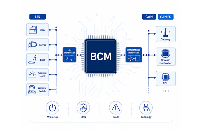
Your body control module may use
LIN transceivers
to connect cost-sensitive local nodes such as doors, mirrors, seats and ambient-lighting modules, while
Classical CAN or CAN FD
connects the BCM to gateways, domain controllers and other ECUs.
Selecting the right transceiver requires more than confirming protocol support. You also need to evaluate
wake-up behavior,
bus-fault tolerance,
automotive EMC performance,
logic-level compatibility and the physical network topology.
LIN Physical Layer
Classical CAN and CAN FD
Selective Wake-Up
Automotive EMC
Transceiver Selection
✓
Quick Selection Guidance
Use
LIN
for low-cost, low-bandwidth body subnetworks. Use
Classical CAN
for robust ECU communication, and consider
CAN FD
when payload size, network utilization or future bandwidth requirements exceed Classical CAN capability. The final data rate must be validated against the selected transceiver, controller, wiring topology and timing budget.
Selection takeaway:
Match the physical-layer device to your BCM network role,
wake-up strategy, and
real vehicle wiring conditions.
Where LIN and CAN Transceivers Sit in a BCM
When you review a BCM network interface, it is important to separate the protocol logic from the physical connection to the vehicle wiring harness. The MCU and communication controller handle messages, timing and protocol rules, while the LIN or CAN transceiver converts those internal logic signals into electrical bus signals that can travel through the vehicle network.
This distinction helps you avoid treating a CAN controller, LIN controller, transceiver, system basis chip and network software as interchangeable components. Each performs a different function, and the correct device must match both your MCU interface and the external bus requirements.
C
CAN Controller
Handles CAN frames, arbitration, timing and error logic inside the MCU or controller.
L
LIN Controller
Manages LIN scheduling, frame handling and communication timing.
T
Transceiver
Converts MCU logic levels into the electrical signals used on the LIN or CAN bus.
SBC
System Basis Chip
Combines a transceiver with selected power, wake-up or supervision functions.
SW
Network Software
Determines which messages are transmitted, received and processed by the BCM.
Keep the interface boundary clear
A CAN controller is not a CAN transceiver, and a LIN schedule is not the LIN physical layer. This page focuses only on the network interface path, not the complete BCM architecture, input AFE, high-side switches, power tree or full signal chain.
LIN vs CAN vs CAN FD in a Body Control Module
You should not treat LIN, Classical CAN and CAN FD as competing versions of the same interface. In a modern BCM, they usually serve different network layers. LIN is commonly used for cost-sensitive local body nodes, while Classical CAN connects the BCM to other ECUs and vehicle gateways. CAN FD becomes relevant when the platform needs larger payloads, more network capacity or additional future bandwidth.
One BCM can therefore use several LIN branches and one or more CAN interfaces at the same time. Your decision should be based on the role of each connection, not only on the maximum communication speed shown in a transceiver datasheet.
Design factor
LIN
Classical CAN
CAN FD
Typical role
Local body subnetwork
Main ECU communication
Higher-capacity ECU network
Common BCM connections
Doors, mirrors, seats and simple actuators
Gateway, cluster and other ECUs
Domain or zone controllers
Network cost
Lower
Moderate
Moderate to higher
Bandwidth need
Low
Moderate
Higher
Physical bus
Single-wire
Differential pair
Differential pair
Typical wake-up
Bus or local wake-up
Bus wake-up
Bus or selective wake-up
Main selection reason
Simplicity and cost
Robust multi-node communication
Payload and network capacity
LIN is not a smaller CAN network
Use LIN bus where local nodes need a simple, predictable and cost-sensitive connection.
Classical CAN remains relevant
A CAN transceiver for BCM may still be the right choice when the existing network capacity is sufficient.
CAN FD speed is a system result
A CAN FD transceiver for BCM may support a high data rate, but the usable speed still depends on topology, timing, wiring and connected nodes.
Define the BCM Network Role Before Selecting a Transceiver
Before you compare transceiver part numbers, first define where the module sits in the vehicle network. A central BCM, a zone controller and a satellite body node may all communicate over LIN or CAN, but their channel count, wake-up behavior, fault-isolation needs and integration priorities can be very different.
This role-first approach prevents you from selecting a device only because it supports the required protocol. It helps you match the BCM network interface to the real number of branches, the expected traffic, the sleep-current target and the consequences of a single interface failure.
CB
Central BCMMultiple vehicle networks
A central BCM may connect several local LIN branches and one or more CAN networks to a gateway or domain controller.
A zone controller may combine higher-capacity CAN FD links with several local LIN networks serving nearby body functions.
Selection priorities
CAN FD capacity · Local LIN channel count · Network latency · Thermal density · Device integration
SN
Satellite Body NodeDoor, mirror or seat module
A satellite node usually needs one simple interface and may prioritize a single-channel BCM LIN transceiver.
Selection priorities
Single-channel LIN · Low cost · Low power · Local wake-up · Minimal external circuitry
Questions to answer before you shortlist a transceiver
1Is the module a central BCM, zone controller or satellite node?
2How many independent LIN branches are required?
3How many CAN networks must the module support?
4Does the interface actually require CAN FD?
5Which local or network events must wake the module?
6Can one interface failure affect another network branch?
How to Select a LIN Transceiver for a BCM
Selecting an automotive LIN transceiver starts with the role of each LIN branch inside your body control module. You need to know whether the BCM serves one local network or several independent door, seat, mirror, HVAC and ambient-lighting branches before you compare individual devices.
Protocol support alone is not enough. A suitable LIN transceiver for BCM must also match your channel count, harness fault conditions, standby-current target, wake-up strategy and MCU logic levels.
LIN Role and Channel Count
First determine how many electrically independent LIN networks your BCM must support. A simple satellite body node may need only one LIN channel, while a central BCM may operate as the LIN commander for several separate branches.
Each independent branch normally requires its own physical-layer channel. Increasing the channel count can reduce connector sharing and improve fault separation, but it also affects PCB area, component count, thermal concentration and the number of devices that must be qualified.
Bus Voltage and Fault Tolerance
Check the normal LIN bus operating range together with every harness fault condition defined by your vehicle platform. Important cases include short to battery, short to ground, battery disturbances and abnormal voltage exposure on both bus-side and logic-side pins.
Do not apply one generic voltage requirement, such as ±42 V, to every design. Your actual limit should come from the OEM electrical specification, vehicle battery architecture, connector exposure and required fault-survival behavior.
Sleep and Wake-Up Behavior
A BCM may remain inactive for long periods, so the transceiver’s sleep and standby behavior directly affects vehicle quiescent current. Compare normal, standby and sleep currents under the same operating conditions instead of relying on a single headline value.
Confirm whether the device supports LIN bus wake-up, local wake-up, a wake-up flag and a clean interrupt path to the MCU. Also check how the device filters noise or incomplete pulses so that harness disturbances do not repeatedly wake the BCM.
Dominant Timeout and Fail-Safe Behavior
A stuck TXD signal or a faulty controller can hold the LIN bus dominant and block communication for every node on that branch. A LIN dominant timeout limits how long the transceiver can keep the bus in this state.
Review the device’s default condition while the MCU is still starting, during undervoltage and when the logic supply is absent. The transceiver should enter a predictable bus-safe state instead of creating false frames or unintentionally holding the network dominant.
Logic-Level Compatibility
Match the MCU I/O voltage to the TXD, RXD, enable and mode-pin thresholds of the transceiver. A device may satisfy every LIN bus requirement but still be unsuitable if its logic interface does not work reliably with your MCU supply.
Pay particular attention to power-off behavior and back-powering. When one device is unpowered, current should not flow through its logic pins in a way that keeps part of the BCM active, violates current limits or creates an undefined bus state.
LIN transceiver selection rule
Choose the channel architecture first, then validate bus faults, low-power LIN transceiver behavior, dominant timeout and logic compatibility. A device that satisfies only the communication-rate requirement is not enough for a production BCM.
Single-Channel vs Multi-Channel LIN Transceivers
If your BCM manages several independent LIN subnetworks, you can use multiple single-channel devices or one integrated multi-channel transceiver. The better option depends on much more than the number of LIN channels shown in the block diagram.
Multiple single-channel devices give you flexible placement and stronger device-level separation. A multi-channel automotive LIN transceiver can reduce component count and centralize the interface, but it may concentrate heat, package dependencies and failure effects in one device.
Consideration
Multiple Single-Channel Devices
Multi-Channel LIN Transceiver
PCB placement
More flexible
More centralized
Component count
Higher
Lower
Fault isolation
Stronger separation by device
Depends on internal device architecture
Thermal concentration
Distributed
Concentrated
BOM simplification
Lower
Higher
Second-source strategy
Often easier
May be more limited
Channel scalability
Add devices as required
Fixed by the selected device
Questions to answer before choosing a multi-channel device
How many independent LIN branches does your BCM actually require?
Can each channel enter sleep and wake independently?
Can one damaged channel affect the remaining branches?
Is the package suitable for your PCB and thermal conditions?
Is an acceptable second source available for the device?
Does the integrated option really reduce external components?
Typical branches may include door networks, seat modules, mirror modules, HVAC actuator networks and ambient-lighting nodes. The decision here concerns only the network interface; motor and lighting drive circuits should be evaluated separately.
How to Select a CAN or CAN FD Transceiver for a BCM
A suitable CAN transceiver for BCM must match the complete vehicle network rather than one isolated data-rate value. Start with the network specification, controller capability and physical topology, then verify fault behavior, common-mode performance and low-power operation.
The choice between Classical CAN and an automotive CAN FD transceiver should be based on the required payload, bus utilization, timing margin and platform roadmap. CAN FD support is useful only when the controller, wiring, termination and other nodes can support the intended network behavior.
Classical CAN or CAN FD
Begin with the vehicle network specification. Confirm whether the BCM controller supports CAN FD and whether the project requires different arbitration-phase and data-phase rates.
Include network length, branch length, node count and propagation-delay budget in the decision. Classical CAN may remain the more appropriate choice when its payload and bus-capacity limits are sufficient.
Data-Rate Capability
Do not select a transceiver only because it advertises a maximum speed such as 5 Mbps or 8 Mbps. That rating describes the device capability under defined conditions, not the guaranteed performance of your complete vehicle network.
Validate the intended data-phase rate against the PCB layout, wiring topology, termination, common-mode choke, TVS capacitance and available timing margin. Every added component can affect signal edges, propagation delay and network stability.
Common-Mode and Differential Behavior
Check the supported CANH and CANL common-mode range together with differential output level, receiver threshold and ground-offset tolerance. These values determine whether the receiver can correctly interpret the bus under real harness conditions.
Propagation delay, loop delay and signal symmetry become increasingly important as the data-phase rate rises. They must fit inside the overall bit-timing budget rather than being reviewed as isolated datasheet parameters.
Bus Fault Handling
Your device review should cover CANH short to battery, CANL short to ground, a short between CANH and CANL, TXD dominant timeout, undervoltage behavior and thermal shutdown.
Also confirm what happens after the fault disappears. Some applications need automatic recovery, while others require the MCU to record the event, change the operating mode or perform a controlled restart.
Standby and Wake-Up Modes
Compare normal, standby and sleep modes together with their supply current, bus behavior and wake-up response. Check whether the device detects general bus activity or supports more selective wake-up behavior.
Review the wake filter, wake flag, MCU interrupt path and any INH or related output. These signals determine how the BCM CAN interface coordinates with the rest of the low-power system.
Selection Area
What You Should Check
Why It Matters in a BCM
Protocol
Classical CAN, CAN FD and controller compatibility
Prevents an unnecessary or incompatible interface choice
Data rate
Actual target rate, propagation delay and timing margin
The advertised maximum rate does not guarantee network performance
Topology
Harness length, branch length, node count and termination
Controls reflection, delay and signal-integrity margin
Common mode
CANH/CANL range, receiver threshold and ground offset
Maintains communication under real vehicle ground conditions
Bus faults
Shorts, dominant timeout, undervoltage and thermal shutdown
Protects the BCM and preserves predictable failure behavior
Low-power modes
Standby, sleep, wake filtering, wake flag and INH output
Supports the vehicle’s quiescent-current and wake-up strategy
CAN FD capability does not define the complete network
Your transceiver, controller, PCB, wiring harness, common-mode choke, TVS diode, termination and connected nodes must all support the intended timing. Treat Classical CAN vs CAN FD as a system decision rather than a single-component comparison.
LIN Wake-Up vs CAN Selective Wake-Up
Your BCM does not need to keep every controller and network interface fully active while the vehicle is parked. A carefully designed
BCM low-power networking
strategy allows the module to sleep while still responding to valid door, key, bus or control events.
The important distinction is that
LIN bus wake-up,
standard CAN bus wake-up and
CAN transceiver selective wake-up
do not use the same trigger logic. You should choose the wake-up method according to the node role, quiescent-current budget and amount of unnecessary network activity your system can tolerate.
LIN Bus and Local Wake-Up
A LIN node can commonly wake when it detects valid bus activity or when a local input changes state. In a door module, for example, a switch press may wake the local node even before the complete body network resumes normal communication.
After wake-up, the LIN commander restores normal frame scheduling and the node returns to its assigned communication cycle. This approach fits localized body functions such as doors, mirrors, seats and simple comfort modules.
Standard CAN Bus Wake-Up
A standard CAN wake-up function detects qualifying activity on the bus and reports the event to the MCU or the module’s power-management path. This allows the BCM to resume operation when another ECU begins communication.
Because general bus activity may wake the node, your design should confirm how the transceiver filters noise, short pulses and incomplete communication patterns. Without suitable filtering, disturbances on the harness can increase false wake-ups and parked-vehicle current consumption.
CAN Selective Wake-Up
With
BCM selective wake-up,
the transceiver does not wake the module for every valid bus event. It evaluates the incoming communication against configured wake-up conditions and activates the BCM only when the required message or pattern is detected.
This can reduce unnecessary ECU activation and is particularly useful when your vehicle uses
CAN partial networking
or has a strict static-current budget. The complete design must still align the transceiver, CAN controller, wake-up configuration and network-management strategy.
Questions to Answer Before Choosing a Wake-Up Strategy
Is normal bus wake-up sufficient for this BCM interface?
Does the vehicle network use partial networking?
Which frames, switches or local events should wake the module?
What happens if the wake-up communication is incomplete or corrupted?
How is the wake-up source reported to the MCU?
Must the MCU remain powered while the transceiver monitors the bus?
Bus Protection, EMC and Signal Integrity
The transceiver is only one part of your
LIN and CAN physical layer.
Once the interface reaches the vehicle connector, protection components, filtering, termination, harness topology and PCB layout can all affect fault survival and communication quality.
Your goal is not to add the maximum number of protective components. You need a network interface that survives the required electrical events while preserving the waveform, timing margin and EMC performance expected by the vehicle platform.
Harness-Side ESD and Transient Protection
Place harness-side protection close to the connector so the surge or ESD current follows a short and controlled path before reaching the transceiver. The bus-pin ratings of the transceiver must still be reviewed together with the external protection network.
When selecting a TVS diode, check its clamping behavior and parasitic capacitance. Excessive capacitance can distort CAN FD edges or alter a LIN waveform, so the device must be evaluated as part of the communication path rather than as an isolated protection component.
Common-Mode Choke Selection
Do not assume that every CAN interface automatically requires a common-mode choke. The decision should come from the OEM EMC target, the transceiver reference design, the wiring environment and actual emissions and immunity testing.
If a choke is used, review its common-mode impedance, parasitic capacitance, current behavior, saturation characteristics and placement. These properties can affect the signal quality of an
automotive CAN FD transceiver,
particularly when the network operates with faster data-phase edges.
CAN Termination and Topology
Confirm where the network termination is placed and whether the vehicle platform uses standard or split termination. The selected approach must match the complete bus rather than the BCM PCB alone.
Review branch length, node position, connector transitions and harness routing because long stubs and poorly controlled branches can create reflection and ringing. These effects reduce timing margin and may become more visible as CAN FD data-phase speed increases.
LIN Pull-Up and Filtering
A LIN commander interface requires an appropriate pull-up network. Check the pull-up resistor, series elements, capacitance and transceiver recommendations together instead of copying one standard circuit into every BCM platform.
Additional filtering may improve EMC performance, but it also changes the bus edge. Your design must preserve a reliable balance between emissions, immunity and communication timing across the complete operating-voltage and temperature range.
Do not add a choke automatically
Use the OEM EMC requirement, reference design and validation results to determine whether a common-mode choke improves the interface.
Check protection capacitance
A protection device can survive the fault and still be unsuitable if its parasitic behavior reduces CAN FD or LIN signal margin.
Validate the complete harness
Termination, stubs, connectors and wiring determine the network result together with the transceiver and PCB.
MCU and Transceiver Interface Compatibility
A transceiver can satisfy every external LIN or CAN requirement and still fail to integrate correctly with your BCM MCU. The logic-side interface must remain predictable during startup, shutdown, undervoltage, sleep and partial-power conditions.
Before you approve an
automotive CAN transceiver
or
automotive LIN transceiver,
check its I/O voltage, default pin states, control-pin behavior and power-off protection against the exact MCU and supply sequence used in your design.
Logic Voltage
Confirm that TXD, RXD and control-pin thresholds match the MCU I/O voltage under all operating conditions.
Separate VIO
Determine whether a dedicated VIO supply is required to interface reliably with a lower-voltage MCU.
Power-Off Behavior
Check whether an unpowered MCU or transceiver can be back-powered through TXD, RXD or another control pin.
Default Bus State
Verify that startup, reset and undervoltage conditions do not force the bus into an unintended dominant state.
Control Pins
Define the required connections and default levels for EN, STB, WAKE, INH and other mode-control pins.
Pull-Up and Pull-Down
Use external biasing where necessary so floating MCU pins cannot select an unsafe or unexpected transceiver mode.
Interface compatibility warning
A transceiver may meet every CAN or LIN bus requirement and still be unsuitable if its logic interface, power-off behavior or default mode conflicts with the BCM MCU. Validate the real startup, shutdown and partial-power sequence before approving the device for your BOM.
Standalone Transceiver vs System Basis Chip
A standalone LIN or CAN transceiver provides the physical-layer connection between your BCM controller and the vehicle bus. It is usually the simplest choice when your design already has suitable regulated rails, wake-up control and system supervision.
A multi-channel transceiver places several physical-layer channels in one package, which can help a central BCM support multiple LIN subnetworks with fewer devices. A System Basis Chip goes further by combining a transceiver with selected power-management, wake-up or supervision functions.
Higher integration can reduce component count and simplify control between communication and low-power modes. However, you should not select an SBC only because it occupies less PCB area. Check which integrated functions you actually need, the resulting thermal concentration, fault dependencies, sourcing options and whether unused functions add unnecessary cost or design constraints.
Device Type
Main Contents
Suitable Situation
Standalone transceiver
LIN or CAN physical layer
The BCM already has regulated rails and supervision
Multi-channel transceiver
Several physical-layer channels
A central BCM must serve multiple subnetworks
System Basis Chip
Transceiver plus selected power or supervision functions
The design benefits from higher integration
Continue with the complete power and SBC design guide
Detailed regulator selection, supervision, reset behavior and BCM power-domain control are covered separately so this page can remain focused on the network interface.
You can use the following semiconductor families to build an initial shortlist for your
BCM LIN transceiver,
automotive CAN transceiver
or
CAN FD transceiver
requirements.
A family name should only guide your search. Before a specific device enters the BOM, verify its current lifecycle status, supported data rate, fault tolerance, wake-up functions, VIO options, temperature grade, qualification and package in the latest manufacturer documentation.
Vendor
Device / Family
Interface
Channels
CAN FD or LIN Rate
Wake-Up Features
Bus-Fault Rating
VIO
Package
Typical BCM Use
Texas Instruments
TLIN family
LIN
Device dependent
Verify current datasheet
Bus/local options vary
Device dependent
Check variant
Check orderable device
Central or satellite LIN node
NXP
LIN transceiver families
LIN
Device dependent
Verify current datasheet
Device dependent
Device dependent
Check variant
Check orderable device
Door, comfort or central BCM branch
Microchip
LIN interface families
LIN
Device dependent
Verify current datasheet
Device dependent
Device dependent
Check variant
Check orderable device
Local LIN body node
Melexis
Single- and multi-channel LIN families
LIN
Single or multiple
Verify current datasheet
Check per channel
Device dependent
Check variant
Check thermal and footprint needs
Central BCM with several LIN branches
Texas Instruments
TCAN family
CAN / CAN FD
Device dependent
Verify exact variant
Standby or selective options vary
Device dependent
Variant dependent
Check orderable device
BCM backbone or gateway connection
NXP
TJA14xx family
CAN / CAN FD
Device dependent
Verify exact device
Wake and partial-networking options vary
Device dependent
Variant dependent
Check orderable device
Central BCM or zone controller
STMicroelectronics
Automotive CAN families
CAN / CAN FD
Device dependent
Verify exact device
Device dependent
Device dependent
Check variant
Check orderable device
Automotive ECU and BCM communication
onsemi
Automotive CAN families
CAN / CAN FD
Device dependent
Verify exact device
Device dependent
Device dependent
Check variant
Check orderable device
BCM or body-domain CAN link
Microchip
CAN interface families
CAN / CAN FD
Device dependent
Verify exact device
Device dependent
Device dependent
Check variant
Check orderable device
Automotive CAN network interface
Verify the exact orderable device
Do not assume that every device in one product family shares the same CAN FD rate, selective wake-up support, VIO option, bus-fault rating, temperature grade or package. Verify each feature in the latest datasheet and product-status page before approving the BOM.
Common BCM Transceiver Selection Mistakes
Most transceiver selection errors occur because one attractive datasheet feature is reviewed without considering the complete
BCM network interface.
Use the following checks to identify risks before they appear during EMC testing, low-power validation or vehicle integration.
The safest selection is not always the most integrated or fastest device
Your best candidate is the device that satisfies the real protocol, timing, wake-up, fault, logic-interface, EMC and sourcing requirements with sufficient validation margin.
BCM Transceiver Design Review Checklist
Use this checklist before you move a
LIN or CAN transceiver for BCM
into schematic review, prototype validation or an RFQ. Each group addresses a different failure path, so a device should not be approved only because it satisfies the first network requirement.
Network Requirements
LIN, Classical CAN or CAN FD? · How many channels? · Central BCM, zone controller or satellite node? · What data rate is required? · What topology must the interface support?
Low-Power Requirements
What is the standby-current budget? · Is bus or local wake-up required? · Is selective wake-up necessary? · Which circuits must remain powered while the BCM sleeps?
Electrical Interface
What MCU I/O voltage is used? · Is a separate VIO required? · What is the default mode? · Does the device provide power-off protection? · Is there a back-powering risk?
Harness and Fault Requirements
Short to battery? · Short to ground? · Required ESD and transient immunity? · Dominant timeout? · Required common-mode or ground-offset range?
EMC and Signal Integrity
Is a common-mode choke needed? · Is TVS capacitance acceptable? · Is termination verified? · Are stub lengths acceptable? · Has the CAN FD timing margin been validated?
Procurement
Does the device have the required automotive qualification and temperature grade? · Is the package suitable, including wettable-flank requirements? · What is its lifecycle status? · Is a second source available? · Are samples and production lead times acceptable?
BCM Transceiver FAQ
FAQs About LIN and CAN Transceivers for BCM Design
These answers help you confirm the most important decisions around the
BCM network interface,
including protocol selection, CAN FD, selective wake-up, EMC filtering and the difference between a standalone transceiver and a system basis chip.
What does a LIN or CAN transceiver do in a BCM?
+
A LIN or CAN transceiver converts the TXD and RXD logic signals used by the BCM controller into the electrical signals required by the vehicle wiring harness. It also receives bus signals and converts them back into logic levels for the MCU. Depending on the device, the transceiver may additionally provide sleep modes, bus wake-up, dominant timeout, thermal protection and bus-fault handling.
When should a BCM use LIN instead of CAN?
+
Use LIN when you need a cost-sensitive, low-bandwidth connection for localized body nodes such as door modules, mirrors, seats, HVAC actuators or ambient-lighting branches. Use CAN when the BCM must communicate reliably with gateways, clusters, domain controllers or multiple peer ECUs. LIN and CAN normally serve different network layers rather than replacing each other directly.
Does every body control module require both LIN and CAN?
+
No. The required interfaces depend on the BCM’s role in the vehicle. A central BCM may need several LIN branches and one or more CAN or CAN FD interfaces. A smaller satellite body node may use only one LIN interface, while a zone controller may combine multiple local LIN networks with a higher-capacity CAN FD connection.
When does a BCM need CAN FD?
+
A BCM may need CAN FD when Classical CAN cannot provide enough payload capacity, network utilization margin or future bandwidth for the vehicle platform. The decision must consider the controller, transceiver, wiring length, branch topology, termination, protection components and timing budget. A transceiver’s advertised maximum rate does not guarantee that the complete network can operate at that speed.
What is selective wake-up in a CAN transceiver?
+
With CAN selective wake-up, the transceiver does not wake the BCM for every valid bus event. It monitors incoming communication and wakes the module only when configured message conditions are met. This can reduce unnecessary ECU activation and helps vehicles with strict standby-current limits or CAN partial-networking strategies.
Should every CAN interface use a common-mode choke?
+
No. A common-mode choke should be selected according to the OEM EMC target, transceiver reference design, wiring environment and validation results. Although it may reduce common-mode noise, its impedance and parasitic capacitance can also affect signal quality. This is especially important for an automotive CAN FD interface with faster data-phase edges.
What is the difference between a standalone transceiver and an SBC?
+
A standalone transceiver mainly provides the LIN or CAN physical-layer interface. A System Basis Chip combines the transceiver with selected functions such as regulation, wake-up control, inhibit outputs or system supervision. An SBC can reduce component count, but it should be selected only when its integrated functions match the BCM architecture, thermal limits and sourcing strategy.
Can a CAN FD transceiver operate on a Classical CAN network?
+
In many designs, a CAN FD-capable transceiver can support Classical CAN physical-layer communication. However, you must verify the specific device, controller configuration, network standard, timing requirements and interoperability with existing nodes. CAN FD transceiver capability does not automatically make a Classical CAN network operate with CAN FD frames or higher data-phase rates.