
BCM Architecture and Body Control Module Block Diagram
Use this page to understand how a typical automotive BCM architecture is organized before you move into component selection or schematic design. You will see how protected vehicle power, local inputs, the MCU, in-vehicle networks, output stages, and diagnostic feedback operate as one coordinated system. The block diagram follows each request from a switch, sensor, or network message through processing and control, then onward to lamps, locks, motors, relays, and remote nodes. It also shows where status and fault information return to the controller, helping you distinguish simple commands from supervised functions. You can also compare centralized, distributed, and zonal body-electronics architectures and understand how each approach changes wiring, module boundaries, and control responsibility. This gives system engineers, hardware designers, and sourcing teams one shared architectural view before detailed IC, circuit, and BOM decisions begin.
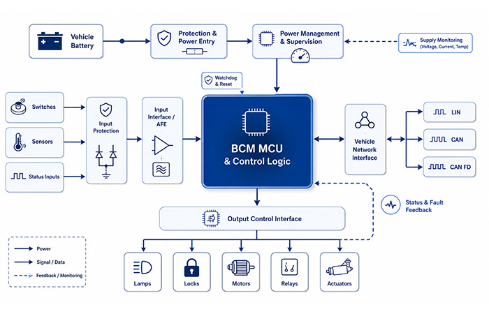
BCM Architecture in One View
A complete BCM hardware architecture is not simply an MCU surrounded by a few peripheral circuits. You are looking at six connected functional domains, each with a distinct input, output, interface, and system boundary. Understanding these boundaries helps you determine where a signal is conditioned, where a decision is made, where power is switched, and where the result is monitored.
Vehicle Power Entry
01This domain creates the protected electrical entry point between the vehicle battery and the BCM’s internal logic, communication, and load-control sections.
- What enters
- Vehicle battery power, wake-related supply paths, and external electrical disturbances.
- What leaves
- Protected battery rails and regulated supplies for logic, interfaces, supervision, and selected output stages.
- What it connects
- The vehicle electrical system to every powered functional domain inside the BCM.
- Why this boundary matters
- Input power protection and supply control cannot be replaced by MCU software because the hardware must remain predictable before, during, and after MCU operation.
Input Acquisition
02This domain converts external vehicle signals into stable, interpretable information that the control logic can evaluate without exposing the MCU directly to the wiring harness.
- What enters
- Switch states, resistor-coded levels, analogue sensor signals, digital status lines, and selected remote-node information.
- What leaves
- Conditioned analogue values, validated logic states, interrupt events, and wake-up indications for the MCU.
- What it connects
- Vehicle switches and sensors to MCU GPIO, ADC, timer, interrupt, or peripheral interfaces.
- Why this boundary matters
- External signals may be noisy, transient-prone, or electrically incompatible with MCU pins, so a dedicated acquisition layer is required before software interpretation begins.
MCU and Control Logic
03This domain combines local inputs, network messages, timing conditions, stored configuration, and system state before producing a controlled response.
- What enters
- Conditioned local inputs, network requests, power-state information, feedback signals, timing events, and configuration data.
- What leaves
- Output commands, PWM requests, network messages, state transitions, diagnostic actions, and sleep or wake-up decisions.
- What it connects
- The input, communication, output, power-supervision, memory, and diagnostic domains through digital and peripheral interfaces.
- Why this boundary matters
- The MCU makes coordinated system decisions, but it depends on separate physical-interface and power stages to safely interact with the vehicle environment.
Vehicle Network Interface
04This domain provides the physical connection between the BCM’s internal logic and external LIN, CAN, CAN FD, or architecture-specific vehicle networks.
- What enters
- Bus-level messages, wake-up activity, status reports, commands, and diagnostic communication from other ECUs or local nodes.
- What leaves
- MCU-compatible communication signals internally and vehicle-bus messages externally.
- What it connects
- The BCM MCU to door modules, lighting nodes, gateways, domain controllers, diagnostic tools, and other vehicle ECUs.
- Why this boundary matters
- The MCU handles communication logic, while the physical network interface handles the electrical bus environment and cannot be replaced by software alone.
Output Control Interface
05This domain converts low-power MCU commands into electrical outputs capable of controlling local lamps, relays, locks, motors, solenoids, and other body loads.
- What enters
- On/off commands, PWM control, direction commands, enable signals, and safety-related control conditions from the MCU.
- What leaves
- Load-level voltage and current paths, relay-coil control, reversible motor commands, and channel-status information.
- What it connects
- The MCU control layer to local physical loads or to interfaces that command remote actuator nodes.
- Why this boundary matters
- MCU pins cannot directly supply or interrupt most automotive load currents, so a separate output-control domain is required for power handling and isolation.
Monitoring and Diagnostic Feedback
06This domain closes the control loop by showing the MCU whether supplies, inputs, communication channels, outputs, and connected loads are operating as expected.
- What enters
- Supply status, watchdog events, input plausibility results, output-state feedback, current information, and network health indicators.
- What leaves
- Fault flags, reset requests, channel-disable actions, degraded operating states, stored events, and diagnostic network messages.
- What it connects
- Power, input, MCU, network, and output domains back into one supervised control and reporting path.
- Why this boundary matters
- Without feedback, the BCM would only issue commands. Monitoring confirms whether the requested result occurred and whether the system should continue, retry, degrade, or report a fault.
The architectural takeaway: you should treat the BCM as a coordinated chain of physical interfaces, processing logic, power-control paths, and supervised feedback—not as a standalone microcontroller. Each domain has a defined electrical and functional boundary, and the complete system only works when those boundaries are designed together.
What a BCM Block Diagram Actually Shows
When you search for a BCM block diagram, you may encounter several types of engineering documents that look similar but serve very different purposes. A functional diagram helps you understand how the main power, input, processing, communication, output, and feedback domains interact. It does not provide every component, pin connection, electrical value, or production-ready circuit detail.
Distinguishing an automotive BCM block diagram from an application diagram, circuit schematic, or reference design helps you choose the correct document for your current design stage.
| Engineering Document | What It Shows | What It Does Not Show |
|---|---|---|
| Functional block diagram | Major functions, system domains, signal directions, power paths, network connections, and feedback relationships. | Exact component connections, pin assignments, passive values, PCB routing, and production circuit details. |
| Application block diagram | IC categories, external interfaces, application functions, and the typical position of each semiconductor block. | A complete validated circuit or a design that can be transferred directly into every vehicle platform. |
| Circuit schematic | Electrical connections, device pins, protection components, passive values, supplies, grounds, and net relationships. | The complete system-level context, vehicle topology, functional ownership, or full software-control relationship. |
| Reference design | A tested implementation that may include schematics, a BOM, PCB files, measurements, software, and design guidance. | A universal production solution that automatically satisfies every vehicle, load, safety, thermal, EMC, and cost requirement. |
What you will see on this page: a system-level and functional BCM architecture, not a vehicle-specific production schematic. The diagram helps you understand how the major domains connect before you proceed to detailed component selection, circuit values, PCB design, and validation.
Typical Automotive BCM Block Diagram
The following body control module block diagram presents the BCM as a closed-loop control system. Vehicle power enters through a protected supply path, while local switches, sensors, and network messages enter through separate physical interfaces. The MCU combines these inputs with stored configuration and vehicle-state logic before issuing commands to local loads or remote nodes.
Follow the arrows to see the five essential paths: power delivery, local input acquisition, network communication, output control, and diagnostic feedback. A separate wake-up path shows how selected inputs or bus activity can bring the BCM from a low-power state into active operation.
Power Path
Follow vehicle battery power through protection and supervision before it reaches the MCU, internal interfaces, always-on circuits, and output-control domains.
Local Input Path
Local switches and sensors pass through protection and signal-conditioning blocks before the MCU can validate and interpret their states.
Network Input Path
LIN, CAN, and CAN FD messages enter through the physical network interface before they are processed by the BCM’s communication and control logic.
Output Command Path
The MCU converts validated requests into commands that the output interface can use to control lamps, locks, motors, relays, and actuators.
Diagnostic Feedback Path
Current, status, supply, and fault information returns to the MCU so the BCM can confirm execution, isolate faults, or report an abnormal condition.
How to Read a BCM Block Diagram
A useful BCM block diagram should help you follow the complete system, not simply show a collection of disconnected boxes. Start with the vehicle power source, then identify where local and network requests enter, where the MCU makes decisions, how output commands reach the loads, and where diagnostic information returns.
The five numbered stages below give you a repeatable way to read almost any body control module design. This approach also helps you identify missing interfaces, incomplete feedback paths, and unclear functional boundaries during an architecture review.
Where Does Power Enter?
Find the vehicle battery, protected power entry, supply supervision, regulated rails, and always-on domain.
Where Do Requests Enter?
Identify local switches, sensor inputs, remote LIN nodes, and CAN or CAN FD messages entering the BCM.
Where Is the Decision Made?
Locate the MCU, memory, state machines, timing functions, configuration data, and control logic.
Where Are Loads Controlled?
Follow MCU commands to the output interface, remote module, load driver, and connected actuator or lamp.
Where Does Feedback Return?
Find current, position, status, fault, supply, and communication feedback returning to the MCU.
End-to-End Signal Flow Through a BCM
A complete BCM signal flow begins when a local switch, sensor, remote LIN node, or another CAN ECU creates a request. The external signal cannot normally be used directly by the MCU, so it first passes through protection, filtering, signal conditioning, or a vehicle-network interface.
The MCU then combines the request with the current vehicle state, feature configuration, network messages, interlock conditions, and previously detected faults. Only after these conditions are validated does the BCM generate a local output command, a remote LIN instruction, or another network message.
The process is complete only when the load or remote node responds and status information returns. This feedback allows the BCM input-output architecture to confirm execution instead of assuming that every issued command was successful.
Example Signal Flow: Power Window Request
A power-window request makes the abstract architecture easier to follow because it combines a local switch, vehicle-state logic, network coordination, motor control, and feedback. When you press the window switch, the electrical state first passes through protection and the local input interface before the MCU interprets the request.
The BCM checks whether the current ignition state, lockout status, available power, network condition, and stored fault state allow the action. In a centralized architecture, the BCM may command a local output stage directly. In a distributed architecture, it may send a LIN message to the door module, which then controls the motor interface.
Current, position, or completion status then returns to the BCM. The controller can continue the movement, stop the motor, store an abnormal event, or report a fault. This section explains the BCM signal path without moving into H-bridge selection, PWM settings, anti-pinch thresholds, or specific motor-driver devices.
What this example shows: the BCM does more than relay a switch state. It protects the input, interprets the request, validates system conditions, selects a local or network-based control path, supervises the resulting movement, and decides how to respond when the expected feedback is missing.
Main Functional Domains Inside a BCM
A complete BCM hardware architecture is formed by several functional domains that work together while maintaining clear electrical and logical boundaries. You can use these boundaries to identify where external vehicle power enters, where local and network requests are accepted, where decisions are made, where loads are controlled, and where status information returns.
The diagram below gives you one horizontal view of the six primary domains. Each block has a different responsibility: it receives a specific type of information or energy, performs a defined function, and passes a controlled result to the next part of the system.
Power Entry and Supply Domain
You should distinguish the external vehicle power source from the regulated supplies used by the BCM’s internal logic. The battery rail is exposed to the vehicle electrical environment, while the MCU, memory, communication interfaces, and signal-processing circuits require controlled internal supply domains.
Always-On and Switched Supply Domains
Some circuits must remain powered so the BCM can detect a wake-up request, preserve selected state information, or supervise essential functions. Other logic and interface domains can remain off until a valid local or network event activates the module.
Logic Power and Load Power
The MCU and low-power interfaces use regulated internal rails. High-current loads may still use a protected vehicle-battery path, with the BCM controlling when and how that path reaches the external load.
Reset and Watchdog Supervision
Reset and watchdog functions belong to the supervision architecture because they help return the MCU and controlled outputs to a predictable state when execution or supply conditions become invalid.
This architecture view does not select buck converters, LDOs, buck-boost devices, voltage values, PMICs, or transient-test limits. Those choices belong to the detailed BCM power-management design stage.
Input Acquisition Domain
A BCM receives more than one type of input. Your architecture should separate physical harness signals from information already received through a vehicle network, because each path requires a different electrical interface before the information reaches the MCU.
Why External Inputs Do Not Connect Directly to the MCU
Harness signals may have incompatible voltage levels, electrical noise, contact bounce, transient disturbances, or fault conditions. The input domain provides the physical boundary that protects and conditions these signals before software evaluates them.
Where Local and Network Inputs Meet
Local signals pass through the connector-side input interface. Network-derived inputs enter through LIN, CAN, or another communication path. Both become software-visible information inside the processing domain, where the MCU can evaluate them together.
Where Validity Is Determined
Hardware establishes an electrically usable signal. Software then evaluates plausibility, timing, permitted combinations, and consistency with vehicle state or related network information.
This architecture layer does not define ADC resolution, filter values, wetting current, threshold calculations, or specific multi-switch detection devices.
Processing and Control Domain
The processing domain is where local inputs, vehicle-network messages, timing conditions, stored configuration, and diagnostic information become coordinated control decisions. The MCU does not merely read a switch and activate an output; it determines whether the requested action is valid within the current vehicle state.
Input and Message Consolidation
The MCU combines conditioned local inputs with LIN, CAN, or CAN FD messages so that one function can depend on several physical and network conditions at the same time.
State Machines and Timing
State machines determine whether a system is inactive, available, operating, blocked, degraded, or faulted. Timers support delays, sequencing, debounce periods, timeout detection, and controlled transitions between these states.
Adjustable Output Commands
PWM channels and timed output logic allow the MCU to request dimming, controlled activation, staged switching, or other variable output behaviour without directly handling load current.
Configuration and Vehicle Variants
Non-volatile storage can preserve configuration, learned values, fault history, and vehicle-specific feature settings. This allows one hardware platform to support several vehicle variants through controlled software configuration.
Sleep and Wake-Up Coordination
The MCU coordinates the transition between low-power and active states. It identifies the wake-up source, enables the required communication and output domains, completes the requested function, stores necessary state, and returns the system to sleep when appropriate.
Communication and Gateway Domain
The communication domain connects local body functions with remote modules, other ECUs, diagnostic tools, and higher-level vehicle controllers. It provides the physical network boundary while the MCU performs message interpretation and coordination.
Local LIN Subnetworks
LIN commonly connects lower-speed local nodes such as door, mirror, seat, sensor, or actuator modules. The BCM may coordinate these nodes as a local network master or body-domain controller.
CAN and CAN FD Connections
CAN or CAN FD can connect the BCM to wider body, comfort, gateway, domain, or central-controller networks. The BCM may receive high-level requests and return function status or fault information.
Network Wake-Up and Status Reporting
Bus activity may act as a wake-up source. After activation, the BCM can process the incoming request, operate local or remote functions, and report the resulting state to other vehicle systems.
Architecture boundary: depending on the E/E architecture, a BCM may act as a body-domain coordinator, a local network master, or a gateway between selected body networks. It should not automatically be described as the central gateway for the entire vehicle.
This architecture view does not define termination, common-mode range, CAN FD data rate, EMC filtering, or individual transceiver selection.
Output Control Domain
MCU pins produce low-power logic commands. They cannot directly control most automotive lamps, motors, relays, locks, heaters, or solenoids. The output domain converts software decisions into electrical actions that can reach a local load or a remote control node.
Local Physical Outputs
A local output controls a load electrically connected to the BCM. The output domain translates a logic command into a controlled current or voltage path suitable for that load class.
Remote Network Commands
In a distributed architecture, the BCM may generate a LIN or CAN command instead of driving the load directly. A nearby door, lighting, seat, or actuator module then performs the physical switching.
Output Status and Fault Feedback
Output interfaces often return state, current, fault, or protection information. This separates high-current load handling from the low-power control domain while preserving a supervised feedback loop.
This architecture view does not calculate RDS(on), thermal impedance, load inrush, high-side versus low-side selection, or individual driver-IC requirements.
Monitoring and Supervision Domain
A BCM is not a one-way output system. It must determine whether the power supply is valid, the MCU is executing correctly, an input is plausible, an output responded to its command, and a connected network node remains available.
Local Hardware Supervision
Peripheral, power, input, or driver hardware can react immediately to an electrical abnormality and return a status or fault indication to the MCU.
MCU-Level Supervision
The MCU evaluates returned status, watchdog events, input consistency, and network availability. It then decides whether the function can continue, should stop, or must operate in a degraded state.
Network-Level Reporting
The BCM can send status or fault information to another ECU, gateway, domain controller, or diagnostic tool so the wider vehicle system can respond appropriately.
This architecture view does not define DTC encoding, open-load thresholds, short-to-ground algorithms, retry counts, or fault-latching strategies.
Hardware and Software Partitioning in a BCM
A clear BCM hardware architecture separates physical electrical responsibilities from software decision-making. Hardware protects, translates, powers, communicates, and switches. Software interprets, validates, sequences, coordinates, and reports.
You should review both layers together because many functions cannot be assigned entirely to hardware or entirely to software. Wake-up control, watchdog supervision, load monitoring, fault recovery, communication health, and functional degradation depend on coordinated behaviour across both layers.
| Responsibility | Hardware Layer | Software Layer |
|---|---|---|
| External signal protection | Protection circuits establish the electrical boundary between the vehicle harness and internal electronics. | Plausibility logic determines whether the resulting signal is valid for the current operating state. |
| Signal acquisition | AFE, ADC, digital-input, timer, or capture interfaces create MCU-readable information. | Filtering, debounce, interpretation, range checks, and state validation convert data into a functional request. |
| Vehicle communication | The physical-layer interface connects internal logic to LIN, CAN, CAN FD, or another supported vehicle network. | Protocol, scheduling, message interpretation, routing, timeout, and application logic manage the information. |
| Load control | Driver and switching stages provide the voltage, current, direction, and physical connection required by the load. | Command logic determines when, for how long, in which sequence, and under which conditions the load operates. |
| Fault handling | Protection mechanisms and fault flags provide immediate physical protection and status information. | Recovery, degradation, logging, retry, shutdown, and reporting strategies determine the system response. |
| Sleep and wake-up | Power domains, wake-capable pins, transceiver wake detection, and reset supervision establish the electrical states. | State coordination, sequencing, source validation, timeout management, and return-to-sleep timing manage the transition. |
Shared Hardware and Software Responsibilities
Centralized BCM Architecture
In a centralized BCM architecture, a large number of local inputs and physical outputs return directly to one primary body control module. The central BCM contains the main processing resources, multiple vehicle-network interfaces, numerous connector pins, and a high concentration of input and output channels.
This structure gives you a clear control hierarchy because one module owns much of the body-function logic. At the same time, it concentrates harness routing, connector density, power dissipation, I/O resources, and PCB complexity at one location.
Advantages of a Centralized BCM
Clear system hierarchy: one primary module owns much of the body-function coordination.
Consolidated functional logic: local inputs, network requests, and output commands can be evaluated in one processing domain.
Fewer major control modules: the architecture may require fewer distributed electronic nodes.
Direct system management: many functions can be supervised from one central diagnostic and software-control point.
Limitations You Need to Consider
Longer and heavier harness paths: many sensors, switches, and loads must route back to one location.
High connector density: the central module needs enough pins and connector space for a large number of channels.
Concentrated PCB and thermal demand: processing, supply regulation, communication, and high-current outputs share one module.
Limited channel expansion: adding new physical functions may require larger connectors, more PCB area, and additional I/O resources.
Distributed Body Electronics Architecture
In a distributed BCM architecture, the central BCM continues to coordinate vehicle-level body functions, but many physical inputs and loads are moved into local electronic modules positioned closer to the equipment they control. A door switch, window motor, mirror actuator, seat function, lighting channel, or HVAC flap no longer needs to route every signal and high-current wire back to one central location.
Instead, a nearby door, seat, mirror, lighting, or HVAC module handles the local electrical interface. The local module reads switches and sensors, controls nearby loads, and exchanges commands, status, and fault information with the central BCM through LIN, CAN, or another platform network.
This allows you to separate local physical control from system-level coordination. The local node owns the immediate input and output relationship, while the central BCM decides how that function interacts with locking, security, lighting, vehicle state, driver settings, and other body systems.
Typical Distributed Signal Path
Local switch or load → local module → LIN or CAN → central BCM → system coordination. The return path carries operating status, completion information, and detected faults back through the same network relationship.
Advantages of Distributed Body Electronics
Shorter local power wiring: loads can connect to modules positioned closer to the door, seat, mirror, lighting assembly, or HVAC mechanism.
Local control near the load: the physical input, switching stage, and feedback path can remain inside one local subsystem.
Modular function development: door, seat, lighting, and HVAC functions can be developed and validated as distinct local nodes.
Central coordination remains available: one central BCM can still align locking, lighting, comfort, security, and vehicle-state behaviour across multiple nodes.
Limitations You Need to Manage
More network nodes: every local module adds another electronic unit, communication relationship, and source of status information.
More complex software coordination: local-node firmware, central-BCM software, message timing, and vehicle-variant configuration must remain compatible.
Unified wake-up management: the system must control which nodes wake, why they wake, how long they remain active, and when they return to sleep.
Cross-node fault isolation: diagnosing a failed function may require checking the local load, local module, communication link, central BCM, and system-level command state.
Zonal Body Controller Architecture
A zonal BCM architecture organizes controllers according to their physical position in the vehicle rather than assigning one controller to each individual function. Sensors, switches, lamps, motors, and other low-voltage loads connect to the nearest front-left, front-right, rear, or cabin zone controller.
Higher-level functions are then coordinated by a central computing platform or domain controller. The zone controller handles local physical interfaces, nearby load control, network access, and selected power-distribution responsibilities, while the central platform manages cross-vehicle logic and software-defined functions.
This means the traditional BCM may no longer exist as one single physical box. Its former responsibilities can be redistributed across several zonal body controllers, with system coordination moved upward into the vehicle’s central software and computing architecture.
How the Traditional BCM Role Changes
Physical location becomes the primary boundary: a zone controller accepts nearby sensors and controls nearby loads regardless of whether they belong to lighting, access, HVAC, or another functional category.
High-level logic moves upward: cross-zone and cross-vehicle functions can be coordinated by a central computing platform or domain controller.
BCM functionality becomes distributed: input acquisition, body-load control, network access, and supervision may be divided across several zone controllers.
Local power distribution may be integrated: the zone controller can combine body control with selected low-voltage power-routing and load-switching responsibilities.
Content boundary: this page explains the architecture-level role of zone controllers. It does not select Ethernet PHYs, define TSN behaviour, compare central-compute processors, design high-speed network protocols, or build a zone-controller BOM. Those topics require dedicated engineering guides.
Centralized vs Distributed vs Zonal BCM Architecture
The main difference between these architectures is not simply how many controllers are used. It is where physical inputs and loads connect, where functional decisions are made, and how wiring, communication, software, power distribution, and diagnostics are divided across the vehicle.
Use the comparison below to decide whether a function should return directly to one centralized BCM, remain inside a nearby functional module, or connect to the nearest zonal body controller.
| Architecture | Control Placement | Wiring Model | Main Advantage | Main Challenge |
|---|---|---|---|---|
| Centralized BCM | One primary body controller owns most local body-function logic. | Many switches, sensors, and loads connect directly through long harness paths. | Consolidated function ownership and a clear system hierarchy. | High connector density, harness concentration, and centralized thermal demand. |
| Distributed body electronics | A central BCM coordinates several local functional modules. | Loads connect to nearby door, seat, lighting, mirror, or HVAC nodes. | Modular local control and shorter physical load wiring. | More network coordination, software versions, wake-up relationships, and cross-node diagnostics. |
| Zonal architecture | Controllers are organized by vehicle location and coordinated by central computing. | Inputs and loads connect to the nearest physical zone. | Lower wiring complexity and a scalable platform for centralized software. | Greater software, network, power-distribution, and platform-integration complexity. |
BCM I/O and Interface Matrix
A useful BCM input-output architecture begins with a complete interface matrix rather than a list of unrelated pins. You need to identify where every request originates, how it enters the controller, which software logic evaluates it, where the resulting command is sent, and what feedback confirms that the function operated correctly.
Inputs and outputs rarely have a simple one-to-one relationship. A single door switch can influence interior lighting, central locking, alarm status, wake-up behaviour, and network reporting. At the same time, one lamp output may depend on a local switch, vehicle speed, ignition state, battery condition, timing logic, and messages received from other ECUs.
Before you begin detailed body control module design, build the I/O matrix together with the feedback requirements. This allows you to distinguish direct physical interfaces from remote network functions and prevents status monitoring from being added too late in the architecture.
| Source or Load | Signal Category | BCM Architecture Block | MCU Interaction | Output or Destination | Feedback |
|---|---|---|---|---|---|
| Door switch | Discrete local input | Input acquisition | GPIO reading, debounce and door-state validation | Interior-light logic, locking state and network status | Confirmed input state |
| Rain sensor | Sensor or network input | Input or communication domain | Sensor-message processing and plausibility evaluation | Wiper request or command to a remote module | Sensor status and message validity |
| Remote unlock command | CAN message | Communication domain | Security state machine and authorization checks | Door-module command or local lock output | Lock position and node response |
| Cabin lamp | Local physical load | Output control | On/off or PWM command with timing logic | Lamp output channel | Current, open-load or fault status |
| Window request | Local or LIN input | Input and network domains | Window state logic, lockout checks and sequencing | Door node or motor-control interface | Position, current and completion status |
One Input Can Influence Several Outputs
A door-open signal can trigger interior lighting, change the alarm state, prevent automatic locking, wake another module, and create a network status message. Your matrix should therefore map one source to every dependent function rather than assigning it to one output only.
One Output Can Depend on Several Conditions
A lamp or motor command may depend on a local switch, another ECU message, current vehicle state, stored configuration, timing conditions, power availability, and existing faults. The output row should identify these dependencies before software and hardware resources are allocated.
Define Feedback at the Same Time as the Command
Do not add monitoring after the output architecture has been finalized. Decide whether the function needs current feedback, position status, network acknowledgement, fault flags, or only an assumed state while the channel and interface requirements are still being defined.
Power, Wake-Up and Sleep Domains
A practical BCM power architecture cannot keep every circuit, network interface, processor resource, and output channel active continuously. The module may remain connected to the vehicle battery for long periods, so the architecture must preserve wake-up capability without allowing unnecessary standby consumption.
The solution is to divide the BCM into several power and operating domains. A small always-on section remains available to detect permitted events. Once a valid wake-up source is identified, the logic and communication domains become active, followed by the output domain required for the requested function.
Your BCM wake-up architecture should therefore define the wake sources, activation sequence, active-state requirements, completion criteria, stored status, and return-to-sleep conditions before detailed power-component selection begins.
Always-On Domain
Maintains the minimum circuitry required for wake detection, essential state retention, supply supervision, and selected network or local-input monitoring.
Wake-Capable Domain
Responds to approved local switches, bus activity, timer events, ignition-related signals, or other configured wake-up sources.
Active Logic Domain
Powers the MCU, memory, communication interfaces, input processing, software services, and the resources needed to evaluate the request.
High-Current Output Domain
Activates only when a lamp, motor, relay, lock, heater, or other controlled load must operate.
Define Every Valid Wake-Up Source
Typical sources may include a door or trunk switch, keyless-entry request, ignition-related input, LIN or CAN activity, timer event, alarm trigger, charging-related event, or another approved system signal. Each source should have a defined validation and activation path.
Architecture boundary: this section defines operating and power domains. It does not select regulators, PMICs, SBCs, switching topologies, transient ratings, or individual low-quiescent-current devices.
Fault Containment and Diagnostic Feedback Architecture
A complete BCM diagnostic architecture does more than detect that something went wrong. It limits the effect of the fault, protects unrelated functions, evaluates whether recovery is possible, and reports the resulting state to the correct software or vehicle-level system.
Fault containment should be planned around architectural boundaries. An abnormal input should not automatically trigger unrelated outputs. One failed load channel should not disable every other body function. A supply-domain problem should result in predictable reset behaviour, and a network failure should have a clearly defined effect on local and network-dependent functions.
The goal of body control module supervision is therefore to move from fault detection to a controlled decision: protect locally, evaluate centrally, select a recovery or degradation strategy, and communicate the final status.
Input Fault
Invalid or implausible input information should be isolated from unrelated output decisions.
Output Fault
One abnormal channel should be disabled or limited without unnecessarily stopping other outputs.
Power Fault
The affected supply domain should be identified and return the system to a predictable state.
Communication Fault
Local functions and network-dependent functions should have clearly separated fallback behaviour.
MCU Fault
Watchdog and reset supervision should recover the controller to a defined operating condition.
Input Fault Containment
An implausible switch, sensor, or network input should be rejected or marked invalid before it propagates into unrelated control functions. Dependent outputs should follow a defined fallback state rather than reacting to uncertain information.
Output Fault Containment
A shorted, overloaded, or non-responsive channel should be isolated at the channel or functional-group level whenever possible. The remaining outputs should continue operating if the architecture allows safe separation.
Power and Reset Behaviour
The architecture should identify which supply domain failed, which circuits remain valid, and how the MCU and outputs return to a predictable state. Undefined resets or chattering output activation should be prevented at the system level.
Communication Fault Boundaries
Separate functions that can operate locally from functions that require a remote command, status message, or network acknowledgement. Loss of one communication path should have a defined and limited effect.
MCU and Watchdog Recovery
When the main program stops executing correctly, supervision hardware should return the MCU and controlled outputs to a known state. Recovery should restore essential operation without creating uncontrolled switching or losing required fault evidence.
Content boundary: this section explains containment and reporting paths. It does not define DTC codes, open-load thresholds, short-to-ground algorithms, retry counts, diagnostic timing, or fault-latching rules.
Functional Partitioning Inside the BCM PCB
A practical BCM PCB architecture should reflect the functional boundaries already defined in the system block diagram. External harness signals, sensitive analogue inputs, network interfaces, processing circuits, power-management paths, and high-current outputs should not be placed randomly across the board.
You can use functional zoning to control how noise, heat, current, transients, signal returns, and diagnostic feedback move through the PCB. The goal is not to create six electrically isolated boards, but to keep incompatible circuit types separated while preserving short, understandable connections between related functions.
The abstract layout below gives you a starting point for BCM hardware design. It shows where each functional region can be positioned without prescribing exact package locations, copper dimensions, layer count, or production routing.
Keep External Protection Close to the Connectors
Harness-facing protection should intercept transients, ESD events, and abnormal external conditions before those disturbances travel deeper into the PCB. Long unprotected traces weaken this boundary and increase the area exposed to external energy.
Separate Sensitive Inputs from High-Current Switching
Analogue inputs, resistor-coded signals, reference nodes, and low-level measurements can be disturbed by switching edges, motor current, relay activity, and load-return voltage. Physical separation reduces coupling before detailed filtering and routing are considered.
Place Network Physical Layers Near Their Bus Connections
LIN and CAN physical interfaces should remain close to their connector region so bus-facing traces stay short and controlled. The MCU-side digital connection can then travel internally through a cleaner logic region.
Keep the MCU Inside a Controlled Logic Area
The MCU and memory should sit between the input, network, power-supervision, and output domains without becoming part of the highest-current routing path. This position supports short digital interfaces while preserving a controlled return environment.
Route Diagnostic Feedback Away from Noisy Switching Nodes
Current, voltage, temperature, and fault-feedback signals may represent small analogue or digital states. They should return to the MCU through controlled paths rather than crossing the most active switching or load-current regions.
Plan Ground Returns by Function
Sensitive input returns, logic returns, communication references, power-management returns, and load-current returns should be planned according to their current and noise behaviour. The architecture should prevent high load current from sharing uncontrolled paths with measurement references.
From Requirements to a BCM Block Diagram
The most reliable way to begin body control module design is to convert vehicle requirements into an architecture before selecting individual ICs. Your block diagram should be the result of controlled decisions about functions, inputs, loads, networks, power states, feedback, and scalability.
Do not begin with a preferred MCU or an existing schematic and then force the vehicle requirements into it. Start with what the BCM must coordinate, build the complete interface lists, select the system topology, and define the relationships between the functional domains.
The workflow below takes you from system scope to a reviewable automotive BCM block diagram. Detailed components, circuit values, PCB routing, software implementation, and validation planning come after the architecture has been agreed.
Define the Controlled Functions
Confirm which functions the BCM owns, which functions it only coordinates, and which functions remain inside another ECU or local module. This establishes the system boundary without repeating a general list of vehicle features.
Build the Input and Wake-Up List
Record every local switch, analogue signal, digital input, frequency input, network message, wake-up source, and expected diagnostic state. Separate direct harness inputs from network-derived information.
Build the Output and Load List
Classify each destination as an on/off load, PWM-controlled load, reversible motor, relay-controlled channel, or remotely controlled network load. Record whether the BCM controls it locally or sends a command to another node.
Select the System Topology
Decide whether inputs and loads return to a centralized BCM, connect to nearby functional modules, or attach to physical zone controllers. The topology determines wiring, connector, network, software, and diagnostic responsibilities.
Partition the Power Domains
Define always-on, wake-capable, active-logic, communication, and high-current output domains. Identify which events activate each domain and which conditions allow it to return to sleep.
Allocate Processing and Interfaces
Verify that the architecture has enough GPIO, ADC inputs, timers, PWM channels, memory, SPI interfaces, LIN controllers, CAN controllers, wake-up sources, and diagnostic paths. This stage checks resource capacity without selecting a specific MCU.
Add Feedback and Supervision Paths
Decide whether each critical function requires state feedback, current monitoring, a fault flag, network acknowledgement, position information, or a plausibility check. Add the return path while the block diagram is still being defined.
Review Scalability
Check whether the architecture can support additional vehicle variants, more channels, new local nodes, extra networks, configuration changes, and later software features without redesigning every functional boundary.
Move from the Block Diagram to the Schematic
After the architecture is approved, you can begin component selection, protection and interface circuit design, power-stage design, PCB zoning and routing, embedded software development, diagnostic implementation, and validation testing.
BCM Architecture Design Review Checklist
Use this BCM design checklist before the architecture moves into detailed schematic development. The review should confirm that every controlled function has a defined source, decision path, destination, power state, feedback requirement, and fault boundary.
A successful automotive BCM architecture review does not ask only whether the required blocks are present. It asks whether the relationships between those blocks remain complete, scalable, diagnosable, and understandable across hardware, software, system, and sourcing teams.
System Scope
□ Are all BCM-controlled functions identified? Confirm that every function has an owner and an explicit relationship with the BCM.
□ Is the architecture centralized, distributed or zonal? The system topology should be selected intentionally rather than emerging from individual circuit decisions.
□ Are local and remote functions clearly separated? Identify which functions are physically controlled inside the BCM and which are coordinated through another node.
Inputs and Interfaces
□ Are all local and network inputs listed? Include switches, sensors, status lines, frequency signals, LIN messages, CAN messages, and configuration inputs.
□ Are all wake-up sources defined? Every wake event should have an electrical path, validation rule, and expected system response.
□ Are analogue, digital and resistor-coded inputs distinguished? Each category requires a different acquisition and validation relationship.
Outputs
□ Are all loads classified by control type? Separate on/off loads, PWM loads, reversible motors, relays, remote commands, and supervised channels.
□ Is each load local or remotely controlled? Confirm whether the BCM drives the physical load or sends a command to another module.
□ Are feedback requirements defined for critical outputs? Decide whether current, position, completion, state, or fault feedback is required.
Power and State Control
□ Are always-on and switched domains separated? Only the resources required for monitoring and wake-up should remain active continuously.
□ Is the sleep-to-active sequence defined? The order for enabling logic, networks, inputs, and outputs should be predictable.
□ Can one power domain fail without disabling unrelated functions? Identify which functions remain available after a local supply or output-domain fault.
Processing and Scalability
□ Are MCU interface resources sufficient? Check GPIO, ADC, PWM, timers, memory, communication controllers, wake sources, and diagnostic interfaces.
□ Can the architecture support multiple vehicle variants? Confirm that configuration differences do not require a completely separate hardware architecture.
□ Is future channel or network expansion possible? Preserve appropriate interface, memory, connector, software, and processing margins.
Diagnostics
□ Are critical status paths closed through feedback? A command should not be treated as confirmed when the architecture requires current, position, state, or acknowledgement feedback.
□ Is local fault containment defined? One failed input, output, supply domain, or communication link should have a controlled and limited effect.
□ Can faults be reported to the appropriate network? Define where the fault is stored, which ECU or tool receives it, and whether related functions need a degraded operating state.
From BCM Architecture Blocks to IC Categories
Once your BCM IC architecture is defined, you can translate each functional block into the semiconductor categories required to implement it. This step connects system architecture with component research without forcing you to select a specific manufacturer or part number too early.
Start by asking what electrical responsibility each block must perform. The power-entry domain needs protection and controlled supply functions. The input domain needs external-signal conditioning. The processing domain needs automotive computation and memory. Communication, output control, and supervision each require their own physical-interface and monitoring devices.
The map below helps you organize body control module components by architecture responsibility. Detailed electrical parameters, qualification requirements, package constraints, pricing, and alternative parts should be evaluated later inside the dedicated subsystem guides.
| BCM Block | Typical IC Category | Architecture Responsibility | Dedicated Guide |
|---|---|---|---|
| Power entry | Protection and power-management ICs | Protected vehicle-battery entry, supply supervision, internal rails and operating-domain control | BCM Power Management and SBC |
| Input acquisition | Input AFE and switch-detection ICs | Protection, conditioning and interpretation of external switches, sensors and status inputs | BCM Input Interface |
| Processing | Automotive MCU and memory | State machines, application logic, timing, configuration, communication handling and fault decisions | Future automotive BCM MCU guide |
| Vehicle networking | LIN, CAN and CAN FD transceivers | Physical connection between MCU communication controllers and external vehicle buses | LIN and CAN Transceivers for BCM |
| Output control | High-side, low-side and motor-driver ICs | Translation of MCU commands into local lamp, relay, solenoid, lock, motor and actuator control | Smart Load Switches for BCM |
| Supervision | Watchdog, reset and monitoring ICs | MCU supervision, predictable reset behaviour, supply monitoring and system-health feedback | BCM Diagnostics and Supervision |
Architecture Before Part Selection
This page intentionally does not list manufacturers, part numbers, current ratings, packages, prices, availability, or replacement devices. Those choices depend on the detailed electrical, thermal, qualification, diagnostic, supply-chain, and commercial requirements of each subsystem.
Download the BCM Architecture and Block Diagram PDF
Use the downloadable BCM architecture PDF when you need to review the system with hardware, software, sourcing, manufacturing, or customer engineering teams. The document brings the main diagrams and design-review steps into one portable engineering reference.
The five-page guide summarizes the complete body control module block diagram, explains the signal and feedback paths, compares centralized, distributed, and zonal topologies, and provides a practical workflow and checklist for architecture reviews.
Page 1 — Complete BCM Architecture Block Diagram: review the relationship between power entry, inputs, MCU processing, vehicle networks, output control and diagnostic feedback.
Page 2 — Signal, Power, Network and Feedback Paths: follow local requests and network messages through the controller and back through supervised status paths.
Page 3 — Centralized, Distributed and Zonal Comparison: compare controller placement, wiring models, functional ownership and platform complexity.
Page 4 — BCM Architecture Design Workflow: move from controlled functions and I/O lists to topology, power domains, processing resources and feedback paths.
Page 5 — Review Checklist and IC Category Map: verify system scope, interfaces, power states, scalability, diagnostics and the semiconductor categories required by each block.
BCM Architecture and Block Diagram PDF
Download the complete five-page engineering reference for design reviews, technical discussions and early architecture planning.
Download the BCM Architecture PDFRelated BCM Engineering Guides
Continue from the system architecture into the subsystem that matches your current design task. Each guide below focuses on one engineering boundary so you can examine detailed interface requirements without mixing network, input, power, load-control and diagnostic decisions on the same page.
Use these pages after the main BCM architecture has been defined and you are ready to investigate the electrical and component requirements of a particular block.
LIN and CAN Transceivers for BCM
Learn how the BCM connects to LIN, CAN and CAN FD networks, how local subnetworks differ from higher-level body networks, and which physical-layer requirements influence transceiver selection.
Explore the network-interface guide →BCM Input Interface and Switch Detection
Examine how discrete switches, resistor-coded inputs, analogue sensors, digital status signals and wake-up inputs are protected, conditioned and interpreted before reaching the MCU.
Explore the input-interface guide →Smart High-Side and Low-Side Switches for BCM
Review the output-stage requirements for lamps, relays, locks, solenoids and other body loads, including load type, protection, diagnostic feedback and thermal considerations.
Explore the load-control guide →BCM Power Management and System Basis Chips
Explore protected battery entry, regulated supply rails, always-on operation, wake-up control, network supervision and the role of system basis chips inside a BCM power architecture.
Explore the power-management guide →BCM Diagnostics and Fault Monitoring
Learn how input, output, supply, communication and MCU faults are detected, contained, evaluated and reported without allowing one abnormal channel to disable unrelated body functions.
Explore the diagnostic guide →Truck Body Control Module Architecture
Examine how truck and commercial-vehicle electrical systems change BCM channel counts, body-network relationships, load requirements, distributed modules and system-integration priorities.
Explore the truck BCM guide →Frequently Asked Questions About BCM Architecture
Use these answers to clarify the main engineering concepts behind a BCM architecture, including functional blocks, signal flow, system topology, hardware boundaries, diagnostic feedback and the transition from a block diagram to detailed implementation.
What are the main blocks in a BCM architecture? +
A typical BCM hardware architecture contains six connected functional domains: vehicle power entry, input acquisition, MCU and control logic, vehicle-network interfaces, output control and monitoring or diagnostic feedback. Power and input domains provide usable energy and information, the MCU evaluates requests, the communication domain exchanges messages, the output domain controls loads, and the feedback domain confirms whether the requested action occurred.
What does a BCM block diagram show? +
A BCM block diagram shows the major functional domains and the paths connecting them. It normally identifies how vehicle power enters the module, how local and network inputs reach the MCU, how control commands reach physical loads or remote nodes, and how status or fault information returns through a diagnostic-feedback path.
Is a BCM block diagram the same as a circuit schematic? +
No. A functional block diagram presents system-level responsibilities and signal relationships. A body control module circuit schematic shows electrical connections, device pins, passive components, supply nets and component values. The block diagram establishes the architecture; the schematic implements that architecture electrically.
How do signals flow through a body control module? +
A request enters through a local switch, sensor, LIN node or another ECU. The signal is protected and converted into an internally usable form. The MCU then validates the request against vehicle state, timing, configuration, network information and active faults. It generates a local output or network command, and the resulting load status, current, position or acknowledgement returns to the MCU to close the BCM signal-flow loop.
What is the role of the MCU in a BCM architecture? +
The MCU combines local inputs, network messages, stored configuration, timing information and diagnostic status. It operates state machines, coordinates sleep and wake-up, processes communication, creates sequenced or PWM output commands and decides how the BCM should respond to abnormal conditions. The MCU provides the decision layer, while separate interface and driver circuits connect it safely to the vehicle.
Does every BCM act as a vehicle gateway? +
No. The role depends on the vehicle’s electrical and electronic architecture. A BCM may operate as a body-domain coordinator, a LIN master, a controller for local physical loads or a gateway between selected body networks. It should not automatically be described as the central gateway for every network in the vehicle.
What is the difference between centralized and distributed BCM architecture? +
In a centralized BCM architecture, many switches, sensors and loads connect directly to one primary controller. In distributed body electronics, the central BCM coordinates nearby door, seat, mirror, lighting or HVAC modules through vehicle networks. Centralized control simplifies functional ownership, while distributed control shortens local wiring and moves physical interfaces closer to the loads.
How does zonal architecture change the traditional BCM? +
In an automotive zonal architecture, controllers are positioned according to physical vehicle areas. Local inputs and loads connect to the nearest zone controller, while a central computing platform coordinates higher-level functions. Traditional BCM responsibilities can therefore be redistributed across several zone controllers instead of remaining inside one body-control module.
Why are BCM input and output stages separated? +
Input stages receive low-level or externally exposed signals that require protection, filtering and interpretation. Output stages must handle higher current, switching noise, heat and load faults. Keeping these domains separate protects the MCU, prevents load-current disturbances from corrupting sensitive inputs and creates clear boundaries between signal acquisition and physical load control.
Why does a BCM need diagnostic feedback? +
Diagnostic feedback allows the BCM to confirm that an output, remote node or supply domain responded as expected. Current, position, state, fault and communication information closes the control loop. It also allows the system to isolate an affected channel, stop or degrade a function and report the abnormal condition without unnecessarily disabling unrelated functions.
What should engineers define before drawing a BCM block diagram? +
Engineers should first define the controlled functions, complete local and network input list, load and output categories, centralized, distributed or zonal topology, vehicle-network connections, wake-up sources, power domains, processing resources and required feedback paths. These requirements establish the functional boundaries that the automotive BCM block diagram must represent.
What comes after the BCM block diagram? +
After the architecture is approved, the project moves into IC and component selection, circuit-schematic development, PCB functional zoning and routing, embedded-software implementation, network and diagnostic configuration, prototype testing and system validation. The block diagram remains the reference used to confirm that the detailed design still follows the approved system boundaries.