
Insulation Monitoring Device: Working Principle and Design
An insulation monitoring device, commonly known as an IMD, continuously monitors the insulation resistance between active conductors and protective earth in an ungrounded electrical system. When insulation resistance falls below a configured threshold, the device generates an alarm or sends a fault signal to the system controller.
IMDs are used in electric vehicles, charging systems, battery energy storage, photovoltaic installations, medical IT networks, and industrial equipment where you need to identify an initial insulation fault before it develops into a more dangerous electrical condition.
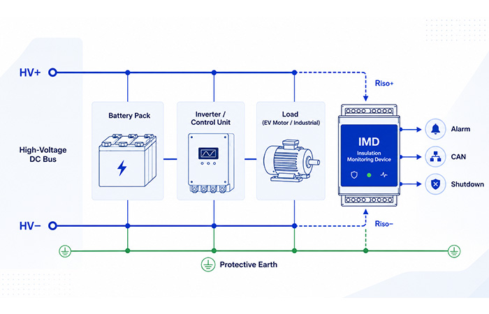
An IMD monitors the insulation paths from the high-voltage conductors to protective earth and sends an alarm, CAN message, or shutdown request when insulation resistance becomes unsafe.
In electric vehicles, the isolated battery bus must remain safely separated from the chassis during startup, driving, charging, and fault conditions. An Insulation Monitoring Device (IMD) for EV HV DC Systems continuously monitors the insulation condition of the battery pack, inverter, traction motor, on-board charger, and high-voltage cabling.
Insulation Monitoring Device at a Glance
Continuously monitors insulation resistance between active conductors and earth.
Ungrounded or impedance-grounded IT electrical systems.
Insulation resistance from the energized system to protective earth.
Alarm, relay output, CAN message, fault code, or controlled shutdown request.
EVs, charging systems, BESS, solar installations, medical networks, and industrial equipment.
High-voltage resistors, switching devices, amplifiers, ADCs, MCUs, and isolated communication.
What Is an Insulation Monitoring Device?
An insulation monitoring device, commonly abbreviated as an IMD, is an electrical safety device that continuously measures the insulation resistance between energized conductors and protective earth in an ungrounded IT system. Unlike a periodic insulation test, an IMD remains connected while the electrical system is operating, allowing you to identify insulation deterioration before it develops into a more serious fault.
Depending on the system architecture, the insulation resistance monitor may evaluate the positive conductor or phase-to-earth path, the negative conductor or neutral-to-earth path, the overall equivalent resistance to earth, and—in some designs—the effect of system leakage capacitance.
Positive-Side Insulation
Measures the resistance between the positive DC conductor or energized phase and protective earth.
Negative-Side Insulation
Measures the resistance between the negative DC conductor or neutral-side conductor and earth.
Total Insulation Resistance
Calculates the combined insulation condition of the complete energized system relative to earth.
System Capacitance
Some monitoring methods also account for leakage capacitance that can influence response time and accuracy.
What Happens When the IMD Detects Low Insulation Resistance?
The IMD converts the measured insulation condition into information that your control system can use. Depending on the application, the output may be an audible or visual warning, a relay contact, a communication message, or a request for a controlled system response.
An IMD does not always disconnect the system immediately. Depending on the application, it may only issue an early warning, or it may send a signal that causes the main controller to reduce power, isolate the high-voltage bus, or perform a controlled shutdown.
Why Are IMDs Used in Ungrounded IT Systems?
In an ungrounded electrical system, a first insulation fault may not produce enough current to trip a conventional protective device. This allows critical equipment to continue operating, but it also means the fault must be detected and corrected before another conductor develops a second connection to earth.
What Is an Ungrounded IT System?
In an IT system, the power source has no direct low-resistance connection to earth, or it is connected through a deliberately high impedance. Because there is no solid earth return path, the current produced by the first insulation fault can remain relatively low.
This arrangement is useful when an unexpected shutdown could create a greater operational or safety risk than temporarily continuing under monitored conditions.
The First Insulation Fault
A first fault occurs when one energized conductor becomes connected to earth through damaged insulation, moisture, contamination, or another low-resistance path.
In an IT system, the resulting current may remain low, so the protective breaker may not trip. The equipment can continue operating, but the system has lost part of its insulation safety margin.
The Risk of a Second Insulation Fault
If another energized conductor develops an earth fault at a different location, the two faults may create a complete current path through protective earth.
The second fault can lead to high current, arcing, equipment damage, electric shock, fire, or an uncontrolled system shutdown. Early detection of the first fault gives you time to inspect and repair the system before this dangerous condition develops.
The first insulation fault may allow an IT system to continue operating, while a second fault can create a high-current path between energized conductors through earth.
How Does an Insulation Monitoring Device Work?
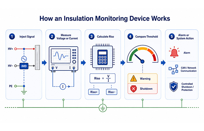
An insulation monitoring device does more than check whether the positive and negative conductors appear balanced relative to earth. It introduces or controls a known measuring condition, observes the electrical response, calculates the insulation resistance, and compares the result with the safety limits configured for your system.
The exact measurement sequence depends on the IMD architecture, but most systems follow the five-stage process below. This approach allows continuous insulation monitoring while the equipment remains energized.
Apply a Measuring Signal
The IMD establishes a controlled measuring path between the energized system and protective earth. Depending on the circuit design, it may apply a DC measuring voltage, a low-frequency AC signal, a pulse, or a switched high-resistance network.
Observe the Electrical Response
After the measuring condition is applied, the IMD observes how the system responds. These measurements show how easily current can flow from the live conductors toward protective earth.
Tracks conductor-to-earth voltage movement.
Detects current through the insulation path.
Observes capacitive settling behavior.
Compares positive and negative conductors.
Determines when the signal has stabilized.
Calculate Insulation Resistance
The controller processes the sampled voltage and current data to estimate the insulation condition of the complete system. Advanced designs can calculate the positive-side resistance, negative-side resistance, and total equivalent resistance separately.
In a real high-voltage insulation monitoring system, the calculation is more complex than this simplified formula. The algorithm may also need to compensate for:
Compare the Result with the Alarm Threshold
Once the insulation resistance has been calculated, the IMD compares the result with one or more configured limits. Multiple levels allow your system to respond progressively instead of treating every fault in the same way.
Generate an Alarm or System Response
When a threshold is crossed, the IMD communicates the result to you or to the main system controller. The final action depends on the application, operating state, and safety strategy.
Common Insulation Monitoring Measurement Principles
Not every IMD uses the same measurement method. The right approach depends on your bus voltage, grounding arrangement, system capacitance, required response time, fault-detection capability, and available circuit complexity.
The following methods are commonly used in EV insulation monitoring, battery energy storage, DC charging, industrial IT networks, and other high-voltage systems.
Passive Voltage Monitoring
Passive monitoring uses a high-resistance divider network and an ADC to measure the positive and negative bus voltages relative to earth. If the bus midpoint shifts significantly, the system may infer that one side has developed a lower insulation resistance.
Simple circuit structure, relatively low component cost, and easy integration with a microcontroller or battery management controller.
It may miss some symmetrical faults, can be influenced by bus-voltage variation, and may not provide accurate individual values for Riso+ and Riso−.
Active DC Signal Injection
An active IMD applies a controlled DC measuring signal between the live system and protective earth. It then measures the resulting current or voltage response to calculate the insulation resistance.
Active measurement does not rely only on natural bus imbalance, provides direct information about the insulation condition, and is suitable for many high-voltage DC systems.
The circuit must limit test energy and leakage current, use high-value high-voltage components, and avoid disturbing other equipment connected to the bus.
Low-Frequency AC Measurement
This method injects a low-frequency alternating or varying signal into the system. The IMD can evaluate the amplitude, phase, settling behavior, or impedance response to distinguish insulation resistance from some capacitive effects.
Useful in complex systems, better suited to networks with significant parasitic capacitance, and capable of separating some resistive and capacitive behavior.
The analog front end and algorithm are more complex, measurement cycles may take longer, and signal integrity becomes more important.
Pulsed or Dynamic Measurement
A dynamic IMD periodically switches the measurement path or changes the applied signal. By comparing voltage or current under multiple known states, the controller can calculate how each side of the bus is connected to earth.
Resistive Bridge Measurement
A resistive bridge uses high-value resistors to create a controlled relationship between the high-voltage bus and earth. By switching resistors or reference conditions and measuring several states, the controller can solve for the system’s insulation resistance.
This method offers a practical balance between cost, circuit complexity, and diagnostic capability. It is commonly considered for automotive high-voltage systems, industrial DC buses, chargers, and battery energy storage equipment using an MCU, ADC, and isolated switching devices.
Insulation Monitoring Measurement Method Comparison
| Measurement Method | Circuit Complexity | Cost | Symmetrical Fault Detection | Capacitive System Tolerance | Typical Use |
|---|---|---|---|---|---|
| Passive Voltage Monitoring | Low | Low | Limited | Limited | Basic DC monitoring |
| Active DC Injection | Medium | Medium | Good | Medium | EV, BESS, industrial DC |
| Low-Frequency AC | High | High | Good | Good | Complex IT systems |
| Pulsed Measurement | Medium | Medium | Good | Medium to good | Automotive and chargers |
| Resistive Bridge | Medium | Low to medium | Good with switching | Design-dependent | High-voltage DC systems |
The most suitable measurement principle depends on the electrical architecture and safety requirements of your application. Higher circuit complexity does not automatically mean better performance unless the method is matched to the system voltage, capacitance, response-time target, and required fault coverage.
Symmetrical and Asymmetrical Insulation Faults
When you evaluate an insulation monitoring device, it is important to understand whether the measurement method can detect both asymmetrical and symmetrical insulation faults. The difference determines whether a simple voltage comparison is sufficient or whether your system needs an active insulation monitoring method.
Both fault types indicate that the electrical insulation between the high-voltage conductors and protective earth has deteriorated. However, they do not create the same voltage behavior, which means they may not be equally visible to a passive monitoring circuit.
Asymmetrical Insulation Fault
An asymmetrical fault occurs when the insulation resistance on one side of the system drops significantly while the opposite side remains at a much higher resistance.
Symmetrical Insulation Fault
A symmetrical fault occurs when the positive-side and negative-side insulation resistances fall to similar values at the same time.
Why Active Measurement Is Important
An active or dynamically switched IMD changes the measurement network and observes the system under several known electrical states. This gives the controller additional information that cannot be obtained from a single passive voltage measurement.
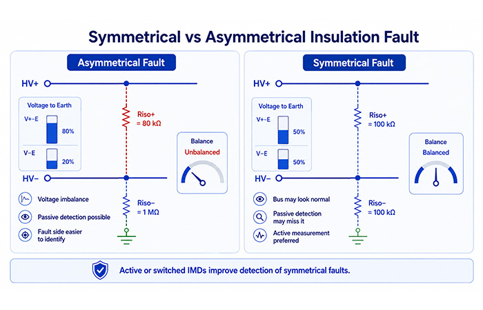
An asymmetrical fault usually shifts the bus voltage relative to earth, while a symmetrical fault can reduce insulation resistance without creating an obvious voltage imbalance.
A complete High-Voltage Energy & Safety architecture combines insulation monitoring, isolated sensing, high-voltage switching, contactor control, surge protection, fault diagnostics, and controlled shutdown.
Insulation Monitoring Device Circuit Architecture
A modern IMD circuit combines a high-voltage measurement path, controlled switching, precision analog signal processing, digital calculation, isolated communication, and fault protection. Each stage must preserve measurement accuracy without creating an unsafe or disruptive leakage path to earth.
The architecture below shows how your measured high-voltage signal moves from the DC bus to the controller and then to the vehicle, charger, battery system, or industrial control network.
Resistor Network
Switching Stage
Conditioning
Calculation Algorithm
Alarm Output
High-Voltage Measurement Network
The measurement network scales the high-voltage bus to a level that your analog front end and ADC can safely process. It also limits the current flowing through the IMD measurement path.
In a high-impedance measurement circuit, PCB cleanliness and moisture can create leakage paths that are comparable to the signal you are trying to measure. Component accuracy alone does not guarantee accurate high-voltage insulation measurement.
High-Voltage Switching Stage
The switching stage changes the measurement path so the IMD can compare multiple circuit states. This is especially important when your system must detect symmetrical faults or calculate positive-side and negative-side insulation resistance separately.
Signal Conditioning Circuit
The signal-conditioning stage buffers the high-impedance measurement network, removes switching noise, scales the signal for the ADC, and protects low-voltage circuitry from abnormal input conditions.
ADC and Microcontroller
The ADC converts the conditioned analog signal into measurement data. The MCU controls the measurement sequence and turns that data into usable insulation-resistance values, diagnostic information, and system responses.
Isolation and Communication
The communication stage transfers insulation data and fault information to the vehicle controller, BMS, charger controller, industrial PLC, or supervisory system while maintaining the required electrical isolation.
Power Supply and Protection
Stable power and coordinated protection are essential because an IMD operates near high-voltage switching equipment, long cables, contactors, inverters, and other sources of electrical transients.
Your protection circuit should prevent transient damage without adding enough capacitance or leakage to distort the insulation resistance measurement. Protection and measurement accuracy must be designed together rather than as separate functions.
Key Components Used in IMD Designs
An insulation monitoring device is not built around one sensor alone. Your design combines a high-voltage measurement network, precision analog circuitry, switching components, data conversion, digital control, isolated communication, auxiliary power, and transient protection.
Each component influences measurement accuracy, response time, leakage current, isolation performance, and long-term reliability. When you select parts for an electric vehicle insulation monitoring system, battery energy storage system, medical IT network, or industrial high-voltage DC bus, you must evaluate the complete signal path rather than choosing each device in isolation.
IMD Component Selection Table
Use this table as a starting point when you define the measurement, control, isolation, and protection architecture.
| Function | Typical Component | Key Selection Factors |
|---|---|---|
| HV measurement | High-voltage resistor network | Voltage rating, tolerance, resistance value, power dissipation, and TCR |
| Measurement switching | PhotoMOS, SSR, or high-voltage MOSFET | Off-state leakage, isolation voltage, blocking voltage, on-resistance, and switching lifetime |
| Signal buffering | Precision operational amplifier | Input bias current, offset voltage, drift, noise, input range, and supply voltage |
| Differential sensing | Differential or isolation amplifier | Common-mode input range, CMRR, gain error, bandwidth, and isolation rating |
| Analog conversion | Precision ADC | Resolution, linearity, input range, reference accuracy, sampling rate, and noise |
| System control | MCU | Integrated ADC, processing capability, CAN, watchdog, self-test, memory, and functional-safety support |
| Communication | Isolated CAN or RS-485 transceiver | Isolation rating, CMTI, bus-fault protection, data rate, and EMC performance |
| Auxiliary power | Isolated DC-DC converter and LDO | Isolation, efficiency, ripple, startup behavior, EMI, load regulation, and thermal performance |
| Protection | TVS diode, ESD diode, fuse, and current-limiting resistor | Surge level, pulse energy, clamping voltage, response time, leakage, and fault current |
Explore Components for Your IMD Signal Chain
Review the device categories that typically support insulation measurement, data conversion, control, isolation, and communication.
Your IMD accuracy depends on the complete measurement chain, including every resistor, switch, amplifier, converter, reference, isolation barrier, and PCB leakage path.
Design Challenges in Insulation Monitoring Systems
Designing an IMD requires you to measure very high insulation resistance while operating beside high common-mode voltage, parasitic capacitance, inverter noise, switching transients, temperature variation, and PCB leakage. These conditions can change the measured signal even when the actual insulation resistance has not changed.
High System Capacitance
Your high-voltage system may contain substantial capacitance to chassis or protective earth. Typical sources include Y capacitors, EMI filters, motor windings, long cables, inverter parasitic capacitance, charger filters, and battery module capacitance.
Measurement Response Time
A fast alarm is important, but increasing measurement speed can reduce accuracy or immunity to noise. Your design must balance several competing objectives.
High Common-Mode Voltage
In a 400V EV platform, 800V traction system, or higher-voltage DC installation, the ADC and MCU operate at only a few volts while the monitored bus may sit hundreds of volts above chassis.
Leakage Current Introduced by the IMD
The IMD measurement network creates its own controlled path between the high-voltage system and chassis. Your design must keep this injected current predictable and low enough that it does not distort the system being monitored.
- Keep the measurement current within a defined and controlled range.
- Avoid influencing the system safety calculation.
- Prevent interference with other insulation or leakage monitoring devices.
- Reduce the risk of false alarms during switching or charging transitions.
- Remain within the leakage limits allowed by the application.
Component Tolerance and Temperature Drift
IMD measurement error is the combined result of the entire analog and physical path. Even small errors become important when you are calculating insulation resistance in the hundreds of kilohms or megohms.
EMC and Switching Noise
Your IMD may operate beside traction inverters, DC-DC converters, motor drives, fast-charger power modules, contactors, relay coils, and long high-voltage cables. These sources can inject both conducted and radiated noise into the measurement path.
Self-Test and Diagnostic Coverage
In a high-reliability system, the IMD must identify not only insulation degradation but also failures inside its own measurement path.
A reliable IMD must distinguish a real insulation fault from capacitance, noise, drift, leakage, contamination, and failures inside the monitoring circuit itself.
Where Are Insulation Monitoring Devices Used?
You use an insulation monitoring device in an unearthed or high-resistance grounded electrical system where the first insulation fault must be detected before it develops into a dangerous second fault, electric-shock hazard, equipment shutdown, or uncontrolled high-voltage event.
The measurement principle may be similar across applications, but the required response time, system capacitance, operating voltage, leakage limit, communication interface, environmental protection, and diagnostic coverage can vary substantially.
Electric Vehicles
In an electric vehicle high-voltage system, the IMD supervises the battery pack, battery junction box, traction inverter, electric motor, HV cables, compressor, PTC heater, and DC-DC converter.
- Insulation check before contactor closing
- Continuous monitoring while driving
- Post-collision safety evaluation
- Maintenance and fault diagnostics
- Support for high-voltage contactor control
On-Board Chargers
An on-board charger insulation monitoring system must account for changing connections between the vehicle-side DC system and the external AC grid.
DC Fast Charging Systems
A DC fast charger IMD may need to monitor the charger output before a vehicle is connected, during precharge, after connection, and throughout high-power charging.
- Output insulation while no vehicle is connected
- Combined charger and vehicle insulation after connection
- Precharge and startup verification
- Monitoring during high-voltage DC output
- Controlled shutdown when a fault is detected
Battery Energy Storage Systems
In a battery energy storage system, insulation faults may develop inside battery racks, the DC bus, PCS equipment, DC distribution, or container-level wiring.
Solar Photovoltaic Systems
IMDs can supervise PV strings, DC combiner boxes, solar inverters, long DC cables, and floating photovoltaic arrays.
Common insulation-fault sources include moisture, damaged cables, aged connectors, module insulation degradation, contamination, and installation errors.
Medical IT Systems
In operating rooms, intensive care units, critical treatment areas, and systems using medical isolation transformers, the first insulation fault should trigger an alarm without immediately interrupting critical power.
The IMD helps you protect patients and equipment while maintaining continuity for essential medical systems.
Industrial Power Systems
Industrial IMDs support continuous insulation supervision in process control systems, mining, chemical plants, manufacturing lines, robotics, industrial DC buses, and emergency power systems.
Early detection helps you schedule maintenance before one insulation fault develops into a production interruption or a second fault with higher safety consequences.
Marine and Railway Systems
Marine electrical networks and railway power systems often combine long cables, vibration, humidity, continuous operation, difficult fault location, and expensive maintenance access.
Continuous insulation monitoring gives your maintenance team an earlier warning before degradation develops into an operational or safety-critical failure.
The correct IMD architecture depends on your bus voltage, system capacitance, allowable leakage current, response-time target, operating environment, and diagnostic requirements.
IMD vs Other Electrical Safety Devices
An insulation monitoring device is only one part of a complete electrical safety strategy. Other devices may measure residual current, test insulation during maintenance, detect an existing ground fault, or locate the faulty branch after an alarm has occurred.
The most important distinction is the electrical system in which the device operates. An IMD is primarily designed for ungrounded IT systems, where you need to detect the first insulation fault before a second fault creates a dangerous current path.
| Device | Main Measurement | Typical System | Online Monitoring | Main Purpose |
|---|---|---|---|---|
| Insulation Monitoring Device | Insulation resistance to earth | Ungrounded IT systems | Yes | Detect the first insulation fault |
| Insulation Resistance Tester | Resistance using a test voltage | De-energized equipment | No | Periodic installation and maintenance testing |
| Residual Current Device | Difference between outgoing and returning current | Grounded AC systems | Yes | Disconnect the circuit during a leakage fault |
| Ground Fault Relay | Ground fault current or voltage | Grounded systems | Yes | Detect and respond to an established ground fault |
| Leakage Current Sensor | AC or DC leakage current | AC or DC electrical systems | Yes | Measure leakage current magnitude |
| Insulation Fault Locator | Fault location within a branch | IT systems with multiple circuits | Yes | Locate the circuit containing the insulation fault |
IMD vs Insulation Resistance Tester
Both devices evaluate insulation resistance, but they are used at different stages of the equipment lifecycle. An IMD remains connected for continuous online insulation monitoring, while an insulation resistance tester is generally used during installation, maintenance, troubleshooting, or periodic inspection.
IMD vs RCD
An IMD and a residual current device solve different safety problems. An IMD is mainly used in an ungrounded IT electrical system, while an RCD is normally installed in a grounded AC system.
It detects a reduction in insulation resistance before a large fault current necessarily exists. The typical objective is early warning, diagnosis, and controlled system action.
It compares the current leaving and returning through the circuit. When the difference exceeds its operating threshold, it rapidly disconnects the supply.
You should not treat an IMD as a direct replacement for an RCD, or an RCD as a replacement for an IMD. The correct device depends on the system grounding arrangement and the type of electrical fault you need to detect.
IMD vs Ground Fault Monitor
A ground fault monitor commonly detects current or voltage produced by a ground fault that has already formed. An IMD focuses on measuring the insulation condition itself, allowing you to detect insulation deterioration while the available fault current may still be too low to activate conventional protection.
How to Select an Insulation Monitoring Device
Selecting an IMD begins with your electrical system, not with a product model number. You need to confirm the bus voltage, grounding arrangement, system capacitance, required response time, supported fault types, communication interface, and applicable safety requirements.
The selection process is especially important for electric vehicle high-voltage systems, DC chargers, battery energy storage, medical IT networks, and industrial equipment where false alarms, slow response, or incomplete fault coverage can affect system availability and safety.
System Voltage
Confirm the maximum normal operating voltage, transient voltage, and whether the system is AC, DC, or a mixed AC/DC network. The IMD measurement circuit and insulation rating must be suitable for every electrical state in which it will operate.
System Grounding Arrangement
Determine how the source and active conductors are connected to earth. An IMD is primarily intended for an ungrounded or impedance-grounded system and may not operate correctly in a solidly grounded network.
Supported System Capacitance
System leakage capacitance affects how quickly the measurement signal settles. A large capacitive network can increase response time, influence measurement accuracy, and require a monitoring method designed for high-capacitance systems.
Measurement Range
Make sure the monitor can measure both healthy high-resistance conditions and the lower resistance values associated with an insulation fault.
Response Time
The required measurement speed depends on when the result is needed and what action the system must take.
Fault Detection Capability
Not every IMD detects the same fault conditions. Confirm that the measurement method covers the faults that matter in your application, including symmetrical insulation faults that may not create an obvious bus-voltage imbalance.
Communication Interface
Choose an interface that can connect the IMD to your BMS, vehicle control unit, charger controller, PLC, supervisory system, or local alarm circuit.
Environmental Conditions
Confirm that the device and its connectors can operate reliably in the physical environment of your equipment.
Compliance Requirements
The alarm threshold, response strategy, diagnostic coverage, and documentation requirements vary by application and region.
Before You Finalize the IMD Selection
Verify the device under the actual system conditions rather than relying only on the nominal bus voltage. Your final evaluation should include capacitance, switching noise, temperature, startup behavior, communication loss, symmetrical faults, and the required system response.
Standards and Safety Requirements
Insulation monitoring thresholds are application-dependent. Some systems use an absolute insulation-resistance value, while others define requirements in ohms per volt. The limits you use may also change according to the system voltage, grounding arrangement, operating state, regional regulations, and OEM safety strategy.
You should therefore treat an IMD threshold as part of the complete system-safety design rather than as a universal value. The monitoring range, warning level, shutdown level, response time, and fault-handling logic must all be verified against the standards and technical requirements that apply to your equipment.
IEC 61557-8
IMDIEC 61557-8 is commonly referenced when you are evaluating insulation monitoring equipment for ungrounded IT systems.
IEC 61557-9
Fault LocationIEC 61557-9 is relevant when your IT system must do more than generate an alarm and also needs to identify the branch in which the insulation fault is located.
IEC 61851-23
DC ChargingIEC 61851-23 is commonly considered in the design and evaluation of DC electric-vehicle charging systems.
UL 2231-2
Personnel ProtectionUL 2231-2 is relevant when you are assessing personnel-protection functions in EV supply circuits and charging equipment.
Values such as 100 Ω/V or 500 Ω/V may appear in specific automotive or charging contexts, but they should not be presented as universal IMD thresholds. The correct warning and shutdown limits must be confirmed against the applicable system standard, operating condition, regional requirement, and OEM safety specification.
Typical IMD Design Workflow
A reliable IMD design begins with the electrical system and safety requirements, not with the selection of an ADC, MCU, or switching device. Each design decision affects the next one, from the maximum bus voltage and system capacitance to the measurement algorithm and final fault response.
The workflow below gives you a practical path for developing an insulation monitoring circuit for an EV, charger, battery energy storage system, medical network, or industrial DC application.
Define the Electrical System
Begin by documenting every electrical condition under which the IMD must operate.
Define Safety Thresholds
Set the resistance levels and timing conditions that determine how your system responds.
Select the Measurement Principle
Choose a method that matches your required fault coverage, capacitance range, response time, and circuit complexity.
Design the High-Voltage Network
Design the measurement path so it can withstand the high-voltage bus while limiting current and preserving accuracy.
Design the Analog Front End
Convert the high-impedance measurement signal into stable data that the ADC can process reliably.
Develop the Measurement Algorithm
The algorithm must coordinate each switching state, wait for the signal to stabilize, and convert raw samples into a dependable insulation-resistance result.
Add Diagnostics and Communication
Add diagnostic coverage so your system can distinguish a real insulation fault from a measurement-path or controller failure.
Validate the Complete System
Validate the IMD under real electrical, environmental, and component-failure conditions before approving the design.
Treat the IMD as a Complete Safety Function
The resistor network, switches, amplifier, ADC, MCU, communication interface, software, and shutdown logic all contribute to the final result. A reliable insulation monitoring system must therefore be validated as one coordinated safety function rather than as a collection of independent components.
Frequently Asked Questions
These answers help you understand how an insulation monitoring device works, where it is used, what it measures, and how it differs from other electrical safety equipment.
What is an insulation monitoring device?
An insulation monitoring device continuously measures the insulation resistance between active conductors and protective earth in an ungrounded IT electrical system. It generates an alarm when the insulation resistance falls below a configured threshold.
How does an insulation monitoring device work?
An IMD applies a measuring signal between the electrical system and protective earth. It then measures the resulting voltage or current response and calculates the system’s insulation resistance.
Where are insulation monitoring devices used?
IMDs are commonly used in electric vehicles, DC charging stations, battery energy storage systems, photovoltaic installations, medical IT systems, industrial power systems, railway systems, and marine equipment.
What does an IMD measure?
An IMD measures the insulation resistance between active electrical conductors and earth. Advanced devices may also estimate the positive-side and negative-side insulation resistance separately as Riso+ and Riso−.
What happens when insulation resistance becomes too low?
The IMD generates an alarm or sends a fault signal to the system controller. Depending on your application, the system may continue operating with a warning, reduce power, disconnect the high-voltage bus, or perform a controlled shutdown.
What is the difference between an IMD and an insulation tester?
An IMD continuously monitors insulation while the system is operating. An insulation resistance tester is generally used during installation or maintenance, often when the equipment is de-energized.
Can an IMD detect symmetrical insulation faults?
An active or dynamically switched IMD can detect symmetrical insulation faults. Simple passive voltage monitoring may fail to detect them because both sides of the DC bus can remain electrically balanced relative to earth.
Why are IMDs used in electric vehicles?
Electric vehicles use isolated high-voltage battery systems. An IMD helps you identify insulation deterioration in the battery pack, inverter, motor, charger, cables, and other high-voltage EV components before the fault becomes dangerous.
What components are used in an IMD circuit?
Typical IMD circuits use high-voltage resistors, solid-state switches, operational amplifiers, ADCs, microcontrollers, isolated communication transceivers, isolated power supplies, and surge-protection devices.
What insulation resistance threshold should an IMD use?
The correct threshold depends on the system voltage, application, operating condition, regional standard, and OEM safety requirements. A value used in one EV or charging system should not automatically be applied to another system.
Engineering note: Always confirm the final insulation-resistance limits, response time, and shutdown strategy against the standards and OEM requirements that apply to your electrical system.