
Answer at a Glance — Should you use eFuse / Hot-Swap?
Choose this page if your design faces high-energy faults, backplane or battery hot-plug, or automotive/industrial transients (cold-crank, load dump). If you only need ramp control, light protection, or ideal-diode OR behavior, go to the PMIC hub → Load Switch / Ideal-Diode OR.
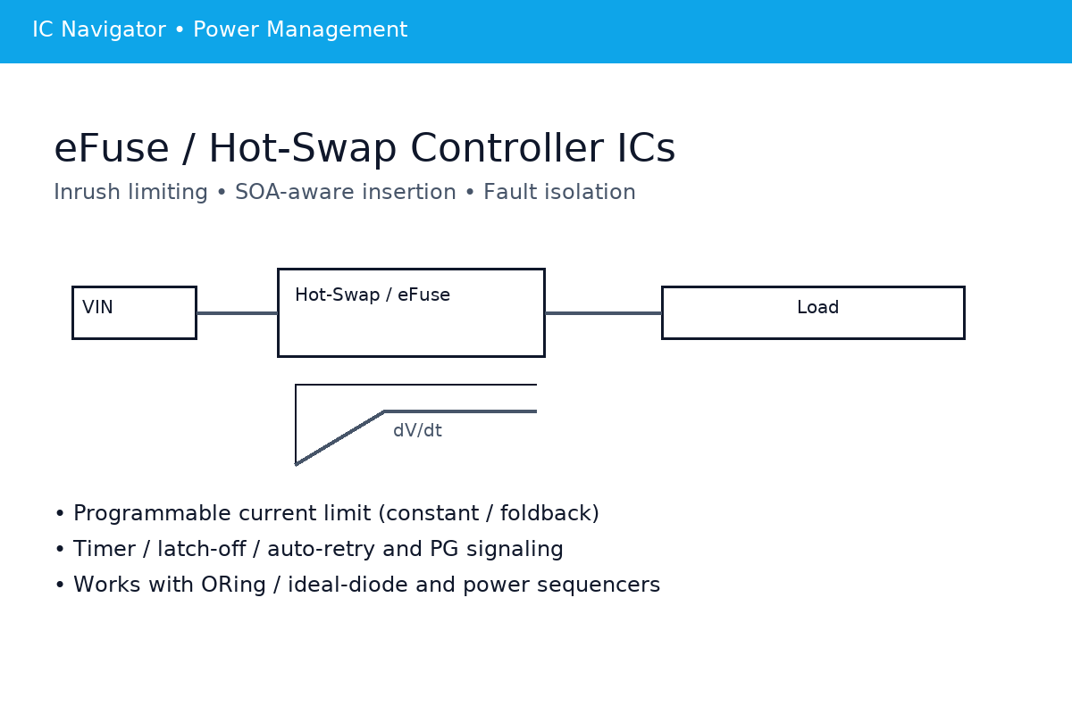
Intro & When to Use
This page focuses on eFuse / Hot-Swap / Surge Stopper solutions for high-energy faults, board-level hot-plug, and automotive/industrial transients. It does not cover low-energy ramp/OR control (see the Load Switch / Ideal-Diode page).
Use this page if you need:
- Backplane / battery hot-plug
- High-energy short-circuit isolation
- Input OV/UV and reverse protection
- Timer / latch / retry fault strategies
- Digital telemetry (PMBus / alarms)
Only need startup dV/dt, small-current protection, or millivolt ORing? Visit the Load Switch / Ideal-Diode OR page.
Topologies
From integrated eFuses to controller + external-FET hot-swap stages. If ORing/priority or digital telemetry is required, see the corresponding variants below.
High-Side eFuse (Integrated Switch)
What it is: Integrated high-side switch with current limit, OV/UV, thermal shutdown, and optional reverse protection (some need external ideal-diode/bridge).
- Core features: CL/foldback/timer limit, soft-start, fault flags.
- Best for: Space-constrained boards with moderate energy.
- Watch-outs: SOA and current are package-limited.
- Tip: Start here when size & BOM dominate the decision.
Hot-Swap (1 or 2 External FETs)
What it is: Controller drives external MOSFET(s) to shape inrush and handle high-energy faults; two back-to-back FETs provide true bidirectional blocking.
- Core features: CL/foldback/timer limit, dV/dt control, PG/alarms, retry/latch.
- Best for: Backplane hot-plug, large Cload, high current.
- Watch-outs: Validate FET SOA vs pulse width & temperature.
- Tip: Start here when Max energy × current drives topology.
Ideal-Diode + Hot-Swap Combo
What it is: Front-end ideal-diode/ORing minimizes drop and blocks backfeed; downstream hot-swap shapes inrush and limits fault energy.
- Core features: Priority/ORing + robust hot-plug & fault handling.
- Best for: Dual-source main/backup switchover systems.
- Watch-outs: Avoid loop interaction—add hysteresis and timers.
- Tip: Use when ORing/priority and hot-plug must coexist.
Digital Telemetry (PMBus / SMBus / Alarms)
What it is: eFuse/hot-swap with digital readouts (V/I/T) and configurable limits via registers; GPIO alarms for fast hardware response.
- Core features: Telemetry, fault logs, remote limit tuning.
- Best for: Platform designs needing visibility and diagnostics.
- Watch-outs: Bus latency vs fault time—keep fast hardware paths.
- Tip: Choose when you need analytics & configurability.
Key Specs & Quick Math
Focus on current limiting, controlled ramp, SOA, sense accuracy, thermal capacity, and transient suppression. Use the quick math below to size parts and screen devices.
ILIMIT modes
- Constant-Current, Foldback, Timer-Limit.
- Trade-offs across startup success, self-heating, and input droop.
dV/dt (Soft-Start)
- Set ramp by external CT / RSLEW or device pins.
- Maps directly to Iinrush with load capacitance.
SOA (Safe Operating Area)
- External FET is constrained by VDS, pulse width, repetition, and temperature.
- Defines the energy ceiling for hot-plug and fault events.
Rsense sizing
- Compute from controller threshold Vlimit: R ≈ Vlimit/Ilimit.
- Check tolerance, power rating, and Kelvin routing.
Inrush & ramp time
- Given target Iinrush, back-calc dV/dt and tramp.
Dissipation & thermal
- Steady vs. limit-mode Pdiss and junction rise.
- Package θJA, copper area, and parallel FET evaluation.
TVS / RC snub
- Clamp voltage ≥ worst-case working voltage (with tolerance) and < device abs. max.
- Match surge energy to TVS rating; RC corner fc=1/(2πRC) to tame spikes.
Iinrush ≈ Cload × dV/dt
tramp ≈ ΔV / (dV/dt)
Rsense ≈ Vlimit / Ilimit
PFET,steady ≈ I² × RDS(on)
PFET,limit ≈ VDS × Ilimit (short pulses)
ΔT ≈ P × θJA
Vclamp ≥ Vmax,work(1+tol) < abs max
Esurge ≤ TVS rated energy (match pulse)
fc = 1/(2πRC)
ILIMIT modes — quick comparison
| Mode | Startup success | Self-heating | Input droop | Tolerance |
|---|---|---|---|---|
| Constant-Current | High with proper dV/dt | Medium–High | Medium | Simple to set |
| Foldback | Medium (verify load start) | Lower (cooler at faults) | Low–Medium | Careful thresholding |
| Timer-Limit | High if ramp ends before timer | Bounded by timeout | Medium–High (during window) | Timer adds robustness |
Design Workflow
Follow this path: define requirements → choose device class → set inrush & protection points → ORing/backfeed policy → PG/EN/alarms → build an experiment table.
- Requirements: VIN range/transients, Ipeak/Irms, load type, hot-plug/backplane, safety, ambient profile.
- Device choice: eFuse vs Hot-Swap (number/size of external FETs), need for PMBus/alarms.
- Inrush & protection points: ILIMIT mode/value, dV/dt, OV/UV, reverse policy, SOA margining.
- ORing / anti-backfeed: combine with ideal-diode / power MUX as needed; add priority, hysteresis, and debounce.
- PG / EN / alarms: PG thresholds, alarm mapping, retry vs. latch strategy.
- Experiment table: test steps, temperature points, hot-plug matrix, recording template (time markers & scope annotations).
Parameter Decision Sheet
Capture ILIMIT, timers, CT/CSS, OV/UV thresholds, SOA headroom, and TVS part numbers. Keep it versioned with BOM changes.
Test Plan (A/B Matrix)
Change only one variable per run: load, capacitance, cable length, source impedance, or temperature. Log pass/fail thresholds and waveforms.
Protection Matrix
Side-by-side comparison across faults and device classes. Each cell summarizes Detection (V/I/T/direction), Action (limit/open/retry/latch), typical Delay, and Waveform notes. PMBus variants add telemetry and alerts.
| Fault Class | eFuse | Hot-Swap (1 FET) | Hot-Swap (2 FET) | Surge Stopper | PMBus Variant |
|---|---|---|---|---|---|
| SCP / SC / OC |
Detect: I via Rsense/amp. Action: CL/foldback; timer → latch or retry. Delay: Gate pull-down <10 µs typical. Waveform: VOUT dip; VDS step; PG deassert. |
Detect: I via sense pin; dV/dt supervised. Action: CL or foldback; timer window. Delay: µs-class gate discharge; ms PG. Waveform: Limited inrush plateau; FET heating. |
Detect: Same as 1FET. Action: Both FETs off → true isolation. Delay: µs; verify no reverse spike. Waveform: Backfeed blocked by series sources. |
Detect: I/V monitor; clamps power. Action: Current clamp & V clamp; timer → off. Delay: Fast analog loop (µs). Waveform: VIN limited; thermal ramp. |
Adds: Read I/V/T; ALERT on OC/SC. Action: Same as base; limits configurable. Note: Bus latency; keep HW fast path. |
| OV / UV |
Detect: VIN comparators. Action: Gate off; optional auto-retry. Delay: µs-ms per filter. Waveform: Clean cutoff; PG toggles. |
Detect: VIN/FB comparators. Action: Turn-off with slew control. Delay: Filtered ms. Waveform: Controlled fall, no bounce. |
Detect: Same; isolation maintained. Action: Dual FET off on OV/UV. Delay: µs-ms. Waveform: No backfeed at UV shutdown. |
Detect: OV by clamp loop. Action: Clamp or disconnect on timeout. Delay: Sub-µs clamp, ms timeout. Waveform: V limited; thermal rise. |
Adds: Thresholds via registers. Report: OV/UV status & logs. |
| Reverse / Backfeed |
Detect: Direction/V drop sense. Action: RCB if available; else off. Delay: µs-class. Waveform: Verify no VOUT→VIN rise. |
Detect: Reverse V across FET. Action: Off; body diode still conducts. Delay: Fast off; not bidirectional block. Waveform: Small backfeed via diode. |
Detect: Reverse sense both sides. Action: Back-to-back FETs block both ways. Delay: µs. Waveform: No reverse spike; clean isolation. |
Detect: Ideal-diode front end (if used). Action: ORing control + cutoff on fault. Delay: Comparator speed (µs). Waveform: mV-level forward drop. |
Adds: Directional alarms; log events. Note: Keep HW path for fast reverse block. |
| Thermal |
Detect: Junction sensor. Action: Thermal shutdown; auto-retry. Delay: Depends on heating time. Waveform: Periodic restart if latched retry. |
Detect: Controller or FET temp proxy. Action: Off or reduce limit window. Waveform: Gate toggles per cooldown. |
Detect: As left; two FETs share heat. Action: Fast off both paths. Waveform: Lower hot-spot if balanced. |
Detect: Internal sensor drives clamp/off. Action: Power limit with timeout. Waveform: Thermal-limited plateau. |
Adds: Read Tj; program thresholds. Report: OT status, history. |
| Timer / Latch / Retry |
Detect: Timer after limit event. Action: Latch-off or auto-retry. Delay: ms scale; set by C/R. Waveform: Sawtooth if hiccup. |
Detect: Programmed window. Action: Off; optional cool-down. Waveform: PG marks retry cadence. |
Detect: Same; dual-path off. Action: Clean isolation on each cycle. Waveform: No backfeed between retries. |
Detect: Energy/time limiter. Action: Clamp then off; restart policy. Waveform: Limited envelope then drop. |
Adds: Program timers; read counters. Report: ALERT on latch/retry. |
Notes on Hot-Swap with two FETs (reverse block & fast power-down)
Back-to-back MOSFETs provide true bidirectional blocking. During power-down or reverse events, ensure both gates are rapidly discharged to avoid body-diode conduction and backfeed spikes. Validate with forced VOUT > VIN tests.
ORing & Muxing Hooks
Interface rules for ideal-diode ORing and power MUX blocks. Keep decision logic, hysteresis, and dwell times decoupled from hot-swap limit/timer loops to avoid oscillation and chatter when sources are close.
Principles
- Priority policy: fixed-primary, voltage-wins, or GPIO-forced override.
- Hysteresis & dwell: add ≥ required mV and ≥ few ms to suppress ping-pong near equal sources.
- Timing decoupling: separate ORing comparator timing from hot-swap limit/timer windows.
- Isolation: for backfeed-sensitive paths, use back-to-back FETs downstream of ORing.
Risks
- Loop interaction: ORing loop fights hot-swap current limit → gate oscillation.
- Insufficient hysteresis: chatter when source voltages converge or cross.
- Delayed cut-off: backfeed spikes if gates are not quickly discharged on power-down.
Suggested Tests
- Main ↔ backup switchover with load steps; verify dwell and hysteresis thresholds.
- Near-equal and crossing source voltages; find the chatter boundary and add margin.
- Reverse and power-down backfeed checks (2-FET isolation downstream of ORing).
Need deeper ORing/MUX design (thresholds, comparators, priority logic)? See the sibling page: Ideal-Diode / Power MUX.
Layout & Thermal
Prioritize the hot loop, measurement integrity, and transient return paths. Keep power and sense routing deliberate, thermals generous, and probing convenient.
Hot loop minimization
Shrink the VIN–FET–VOUT loop; route input and return in parallel with tight coupling. Place CIN/COUT close to switch nodes to tame di/dt and ringing.
Kelvin Rsense
Use four-terminal sensing; run matched differential traces to the controller. Keep them away from high-current returns. Land on dedicated sense pads (no shared via barrels).
TVS / RC placement
Place the TVS at the input connector; ensure a short, straight return to chassis/ground. Keep any RC snub loop tiny and close to the switching edge you need to damp.
Star grounds (PGND/AGND)
Feed comparators/controllers from a clean AGND. Star back to PGND at a quiet node; Kelvin Sense/PG pins; avoid dropping measurement currents into power ground.
Thermal path
Use large copper under FETs with via arrays. Parallel FETs need symmetric copper to share current. Align hot parts with airflow; avoid trapping heat under tall components.
Probing points
Provide labeled pads for VIN, VOUT, PG, CS, EN, ALARM and a nearby ground spring. Reserve scope space; mark current direction and measurement polarity.
Quick Checklist (Copy-Paste)
- Minimize VIN–FET–VOUT loop; pair input/return.
- Kelvin four-terminal Rsense; matched differential traces.
- TVS at connector; short straight return; tiny RC loop.
- Star AGND to PGND; clean comparator references.
- Large copper + via arrays; symmetric for parallel FETs.
- Test pads for VIN/VOUT/PG/CS/EN/ALARM with GND spring.
Validation & Bring-Up
Use a one-variable-at-a-time approach; log scope markers and ambient. Build an A/B matrix and capture limits, waveforms, and pass/fail criteria.
Startup waveform
Measure dV/dt and Iinrush; check input droop and PG timing. Confirm ramp ends before any timer-limit window expires.
Over-current
Validate CC/foldback/timer actions and recovery policy. Record latch vs. retry cadence and junction heating rate.
Thermal shock
Under steady and pulsed limit, log Pdiss → ΔT and thermal shutdown points. Measure cool-down time to restart.
Hot-plug
Exercise battery/backplane insert/remove with/without load and input transients. Verify gate discharge speed and no backfeed spikes.
ORing behavior
Main↔backup switchover under load steps; sweep near-equal sources to find chatter threshold; test power-down backfeed.
EMI & transients
Capture switching spikes, cable resonance, and TVS clamping. Tune RC snub and routing where necessary.
A/B Conditions Matrix
| Run | Temp | Cable | Variable | Cload | Source Z | Notes |
|---|---|---|---|---|---|---|
| A1 | 25 °C | 0.5 m | dV/dt | 220 µF | 50 mΩ | Base bring-up |
| A2 | 25 °C | 0.5 m | Ilimit | 220 µF | 50 mΩ | CL vs foldback |
| B1 | -20 °C | 1.0 m | Load step | 220 µF | 100 mΩ | ORing switchover |
Bring-Up Checklist
- Log VIN, VOUT, I, VDS, GATE; mark time zero and trigger conditions.
- Record thresholds (OV/UV, Ilimit, timers), ambient, and airflow.
- Save scope screenshots with scale annotations and cursor readouts.
- Note pass/fail margins and ΔT at steady and pulsed limits.
- Attach A/B matrix, serial numbers, and configuration hash.
Cross-Brand IC Options
Series-level index only—no part-number deep dive here. Use this as a quick map to eFuse, Hot-Swap, Surge Stopper, Ideal-Diode/OR, and high-side distribution families. For pin-compatible swaps or a vetted shortlist, head to Resources & RFQ and Submit BOM (48h).
Texas Instruments (TI)
- TPS259x / TPS266x — eFuse Industrial 12–60 V rails; OV/UV/ILIM/timer for fast bring-up.
- LM506x — Hot-Swap Controller External FET(s); high-energy backplane hot-plug.
- TPS27xxx — High-Side Switch Power distribution, multi-channel variants.
Analog Devices (ADI)
- LTC436x — Surge Stopper Input clamp/ride-through for automotive/industrial.
- LTC422x / LTC421x — Hot-Swap Inrush control, fault timers, SOA-friendly with external FETs.
- LTC435x — Ideal-Diode / OR Controller mV drop, backfeed block, priority hooks.
STMicroelectronics (ST)
- STEFxx — eFuse 5–24 V classes; USB/PC/industrial protection.
- VIPower (selected) — Hot-Swap / Protection Higher-current protection options.
onsemi
- NISxxx — eFuse / Protected Switch Integrated ILIM & thermal; compact BOM.
Renesas
- ISL614x / ISL612x — Hot-Swap / Power-Path Back-to-back FET support, PG/alarms.
Microchip
- MIC25xx / MIC20xx — High-Side Distribution / Protected Switch Some parts approach eFuse behavior.
- MCP16xx — Ideal-Diode / Power-Path Series-dependent; check datasheet limits.
NXP
- NX5P-series — USB / 5 V Power-Path Light/medium loads; limited fault energy.
FAQs
Short, practical answers covering eFuse, Hot-Swap, Surge Stopper, current limiting, SOA, Kelvin sensing, ORing, PMBus telemetry, validation, and replacements. Expand any item for actionable guidance and links to the relevant sections of this page.
What’s the boundary between an eFuse, a Hot-Swap controller, and a Surge Stopper?
How do I pick among constant-current, foldback, and timer-limit modes?
How do I back-solve dV/dt and ramp time from Cload and a target inrush current?
How do I read SOA curves with pulse-width and temperature derating?
How should I select Rsense, and why does Kelvin routing matter?
How do I prioritize actions for reverse/backfeed, OV/UV, and short events?
How do I prevent gate oscillation or chatter with ORing plus Hot-Swap?
What’s the quick math and placement rule for TVS and RC snubbers?
Thermal shutdown with retry or latch—what are the system side effects?
How should I structure backplane hot-plug A/B tests?
What does PMBus/telemetry add during design and debug?
How do I validate backfeed blocking and power-down behavior with 2-FET isolation?
How do I choose ORing thresholds and hysteresis for near-equal sources?
How do I estimate FET temperature rise and decide on copper, vias, or paralleling?
How do I check replacements for compatibility: slopes, thresholds, timing, thermals?
Resources & RFQ
Download worksheets and quick guides, then send your BOM for a curated cross-brand shortlist within 48 hours.
Selection Worksheet (PDF)
Step-by-step fields for limits, dV/dt, SOA margin, and thresholds.
Download: ls-idor-selection-worksheet.pdfdV/dt & Inrush Calculator (Excel)
Back-solve ramp time from Cload and target Iinrush; quick droop check.
Download: ls-idor-inrush-calculator.xlsxORing FET Sizing Quick Guide (PDF)
Forward drop, backfeed block, and SOA checks for ideal-diode paths.
Download: ls-idor-oring-fet-sizing.pdfBring-Up Checklist (PDF)
Scope channels, thresholds, timing, ΔT, and screenshot standards.
Download: ls-idor-bringup-checklist.pdf