
What Is a BCM on a Truck?
Truck Body Control Module Functions, 24V Systems and IC Selection
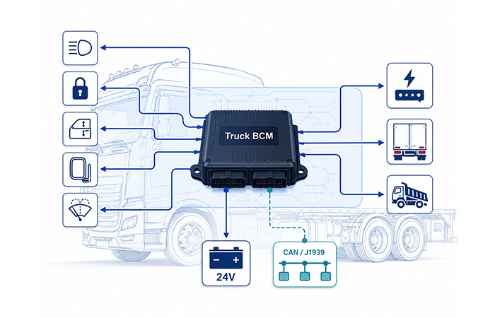
A truck BCM, short for Body Control Module, is an ECU that manages or coordinates many non-powertrain electrical functions across the cab and vehicle body. Depending on the platform, it may control lighting, door locks, windows, mirrors, wipers and auxiliary equipment while exchanging commands and operating status with other controllers through CAN or SAE J1939 networks.
Quick Answer: Truck BCM at a Glance
Use this quick reference to understand what a truck BCM is, which vehicle functions it may manage and how it fits into a modern commercial-vehicle electrical system.
What Is a Body Control Module on a Truck?
A truck Body Control Module (BCM) is an electronic control unit that helps you manage the electrical functions associated with the truck cab, vehicle body and selected auxiliary equipment. Unlike an engine control module, it is mainly concerned with non-powertrain electrical functions such as lighting, access, visibility and driver-comfort systems.
When you operate a switch, unlock a door or activate the wipers, the truck BCM module may receive the request directly from a physical input or indirectly through a vehicle network. It evaluates that request together with information from sensors and other controllers before driving the load itself or sending a command to a local control module.
The exact responsibilities of a commercial vehicle body control module depend on the truck platform. Some vehicles use one central BCM, while others divide the work between a cab controller, door modules, lighting controllers, trailer modules and body-builder interfaces. This is why you should always match the BCM architecture to the actual functions, network layout and electrical loads of your vehicle.
What Else Is a Truck BCM Called?
When you review an OEM schematic, component list or commercial-vehicle service document, you may not always see the exact term truck body control module. Manufacturers use different names depending on how the vehicle divides cab, body, power-distribution and network-control functions.
Common names include Body Control Module, Body Controller, Cab Control Module, Cab Controller, Body Computer, Central Electrical Unit and Vehicle Electrical Control Unit. These names can describe similar functions, but they are not automatically interchangeable.
When you compare modules or source replacement ICs, confirm the actual inputs, outputs, network interfaces and controlled loads instead of relying on the module name alone.
What Does a BCM Control on a Truck?
A truck BCM may control electrical loads directly, or it may coordinate separate door, lighting, trailer and cab modules through the vehicle network. The exact function split depends on the truck manufacturer, cab configuration and overall commercial-vehicle electrical architecture.
Lighting and Signalling
Depending on the vehicle architecture, the BCM may control or coordinate interior cab lights, dome and reading lamps, step and courtesy lighting, marker and clearance lamps, turn signals, hazard lights, selected exterior lighting and trailer-lighting commands or supervision.
Access and Security
The module may manage power door locks, central locking, keyless-entry requests, door and latch monitoring, alarm coordination, storage-compartment locks and immobilizer status coordination, either directly or through local access-control modules.
Windows, Mirrors and Visibility
A truck body control module may coordinate power windows, window lockout, mirror adjustment, mirror heating, mirror folding, windshield wipers, washer pumps and intermittent-wiping functions.
Cab Comfort and Convenience
The BCM may coordinate accessory power, seat-heating requests, HVAC control requests, cab fan or flap commands, courtesy-delay functions, power outlets and timed accessory shutdown.
Sleeper-Cab Functions
On long-haul trucks, the BCM may manage or coordinate sleeper-cab lighting, auxiliary power outlets, parking-mode comfort loads, auxiliary heater requests, timed cabin accessories and battery-protection functions.
Trailer and Body-Builder Functions
Depending on the body and trailer configuration, the module may coordinate trailer lighting, liftgate requests, cargo-body status signals, auxiliary-equipment enable functions, body-builder interface inputs, warning lamps, interlocks and selected PTO-related requests or status information.
Where Is the BCM Located on a Truck?
There is no single mounting position used by every truck manufacturer. A truck BCM module is normally installed inside a protected area of the cab, close to the wiring harnesses, fuse center, relay box or other electrical-control modules it needs to connect with.
Depending on the truck make, model, cab configuration and electrical architecture, you may find it behind or below the dashboard, near the cab fuse and relay center, beneath or behind a seat, inside an electrical compartment or integrated into a central electrical unit.
Is a Truck BCM the Same as an ECU?
A truck BCM is a type of electronic control unit, but not every ECU is a BCM. ECU is a broad term for any electronic module that controls a specific vehicle system. The BCM is the ECU that focuses primarily on cab, body, lighting, access, visibility and selected convenience functions.
A truck BCM is an ECU, but an ECU is not necessarily a BCM.
When you review a truck schematic or BOM, the module name tells you which vehicle domain it is responsible for. An engine control module manages engine operation, while a body control module manages or coordinates non-powertrain electrical functions.
Does the Truck BCM Control the Engine?
A truck body control module normally does not directly control the engine or transmission. Fuel injection, combustion, torque management, turbocharger control and transmission shifting are usually handled by the ECM and TCM.
However, the BCM still needs vehicle-status information before it can make body-control decisions. It may receive ignition status, engine-running status, vehicle speed, charging-system information, brake status and wake-up or shutdown commands from the ECM, TCM, gateway or other network controllers.
The Truck BCM Usually Does Not Directly Control
Information the Truck BCM May Receive
The BCM can then use this information to coordinate lighting, door locks, wipers and accessory power. For example, it may enable daytime lighting after receiving an engine-running message, or disable selected accessories when the truck enters a shutdown state.
How Does a Truck BCM Work?
A truck BCM works by collecting requests and vehicle-status information, evaluating those signals through its MCU and control logic, and then operating a load directly or sending a command to another module.
Inputs can arrive from switches, sensors or CAN and J1939 network messages. Outputs may go to relays, smart high-side or low-side switches, motors, lamps or local control modules. Diagnostic feedback allows the BCM to confirm whether the requested function was completed correctly.
Example: The Driver Activates the Wipers
The wiper example shows how a simple driver request can involve several checks before the load is activated. Depending on the truck architecture, the BCM may control the wiper output directly or coordinate a separate wiper controller through the vehicle network.
You move the windshield-wiper switch to the required speed or intermittent setting.
The truck BCM reads the switch input directly or receives the request from a local steering-column or cab module.
The BCM checks ignition status, vehicle operating mode and any required network conditions.
It activates a relay or smart driver directly, or sends a CAN or J1939 command to a local wiper controller.
The wiper driver or local module powers the motor and executes the requested speed or interval.
Operating status and fault feedback return to the BCM so it can confirm movement, detect a fault or report a diagnostic condition.
How Does a Truck BCM Communicate With Other Modules?
A truck body control module rarely operates as an isolated controller. It exchanges vehicle-status information with major ECUs, communicates with local cab modules and connects directly to switches, sensors and electrical loads.
The communication path depends on the truck architecture. CAN and SAE J1939 are commonly used for vehicle-level data, LIN may connect lower-cost local nodes, and direct electrical inputs and outputs are used when the BCM needs to read or control a physical signal without another networked module.
CAN and SAE J1939
In a commercial truck, CAN and SAE J1939 communication allow the BCM to coordinate body functions with the engine, transmission, chassis, instrument cluster and central gateway.
LIN and Local Subnetworks
LIN local subnetworks may be used where the truck needs a simpler, lower-cost connection between the main BCM and nearby cab modules.
Direct Inputs and Outputs
Not every function needs a network connection. The BCM may read direct switch and sensor inputs and may drive lamps, relays, motors or solenoids directly through protected output stages.
How Does a Truck BCM Help Prevent Battery Drain?
A truck may remain parked for long periods while security, remote-entry and selected sleeper-cab functions still need power. The truck BCM helps manage this transition by deciding which functions remain available and which non-essential loads should be switched off.
Depending on the vehicle architecture, it may monitor supply voltage, coordinate module sleep and wake-up, turn off timed accessories and apply low-voltage load shedding when the battery needs protection.
Monitor Supply or Battery Voltage
The BCM may use supply-voltage information to decide when comfort or auxiliary functions should be limited.
Coordinate Module Sleep and Wake-Up
The BCM helps other modules enter a low-power state and wake only when a valid switch, timer, keyless-entry or network request is detected.
Turn Off Timed Accessories
Courtesy lighting, power outlets and selected cabin accessories can remain active briefly before the BCM switches them off.
Shed Non-Essential Loads
If voltage falls below a defined threshold, non-critical comfort functions may be disabled before security and essential wake-up functions.
Prevent Modules From Remaining Awake
The BCM can help identify or isolate a network state that would otherwise keep multiple controllers active after shutdown.
Maintain Security and Wake-Up Functions
Door locking, alarm monitoring, keyless-entry reception and selected wake-up inputs can remain available while most other modules sleep.
Example Parking Sequence
A typical parking sequence shows how the BCM gradually moves the truck from normal operation into a controlled low-power state without immediately removing every convenience and security function.
You switch off the ignition and leave the truck.
The BCM temporarily keeps courtesy lighting, accessory power and selected cabin functions available.
After the programmed delay, it switches off non-essential timed loads.
The vehicle network and connected controllers gradually enter their low-power sleep states.
Door locks, alarm monitoring and essential wake-up inputs remain active.
If battery voltage falls further, the BCM may restrict additional comfort or auxiliary loads.
Truck BCM vs Passenger-Car BCM
A truck BCM and a passenger-car BCM perform the same basic role: they manage or coordinate body-related electrical functions. However, you cannot assume that a BCM designed for a 12V passenger car will meet the electrical, environmental and lifecycle requirements of a heavy-duty truck.
When you select components for a commercial vehicle body control module, you need to consider longer wiring harnesses, 24V electrical systems, trailer connections, sleeper-cab operation, higher vibration and much longer operating hours.
| Design area | Passenger-car BCM | Truck BCM |
|---|---|---|
| Nominal voltage | Commonly 12V | Commonly 24V, although some commercial platforms use 12V |
| Wiring | Shorter body wiring harnesses | Longer cab, chassis and trailer wiring with greater voltage drop and noise exposure |
| Network | LIN, CAN and CAN FD | CAN and SAE J1939 with distributed cab, chassis and auxiliary nodes |
| Functions | Body, access and comfort functions | Cab, trailer, auxiliary and body-builder functions |
| Duty cycle | Typical passenger-vehicle operation | Long operating hours, high annual mileage and frequent electrical cycling |
| Environment | Standard automotive environmental conditions | Higher vibration, wider exposure and more demanding thermal conditions |
| Parking operation | Normal accessory-delay functions | Sleeper-cab loads and extended parked operation with battery protection |
| Vehicle variants | More standardized body configurations | More custom bodies, trailers, liftgates and auxiliary equipment |
For your design, the key difference is not simply 12V versus 24V. A heavy-duty truck BCM must remain reliable across longer harnesses, harsher transients, extended standby periods and a wider range of vehicle configurations.
Why 24V Commercial Vehicles Need Different BCM Design
A 24V truck electrical system does more than increase the nominal supply voltage. It changes the voltage range, transient exposure, load behavior and protection requirements that your truck body control module must tolerate.
Your BCM must continue operating predictably when the truck experiences long wiring runs, high-current lamp or motor loads, trailer-connector faults, ground-potential differences and extended parked operation. These system-level conditions influence the voltage ratings, protection features, diagnostics and standby behavior required from the selected ICs.
Wider Operating-Voltage Conditions
You need sufficient operating margin for charging voltage, low-voltage conditions, jump-start events and other variations around the nominal 24V supply.
Higher Transient-Energy Exposure
Long harnesses, inductive loads and commercial-vehicle operating conditions can expose BCM-connected pins to stronger electrical disturbances.
Long-Harness Voltage Drop
Cab, chassis and trailer wiring can introduce voltage drop, noise pickup and signal-reference differences that are less significant in shorter passenger-car harnesses.
Trailer-Connector Faults
External connectors can be exposed to moisture, corrosion, wiring mistakes and shorts, so trailer-related outputs need robust protection and diagnostics.
Ground-Potential Differences
Long current-return paths and multiple grounding points can create offsets between the cab, chassis, trailer and connected body equipment.
High Lamp and Motor Inrush
Cold lamps, blowers, wipers, pumps and motors may draw substantially more current at startup than during normal operation.
Stronger EMC Requirements
Longer wiring and higher-current switching create more opportunities for emissions, conducted disturbances and immunity problems.
Wide Temperature Range and High Vibration
Component qualification, package robustness and connector design must reflect the mounting location and actual commercial-vehicle environment.
Extended Standby Periods
Your BCM must preserve security and wake-up functions while keeping quiescent current low during long parking periods.
Long Production and Service Lifecycle
Commercial vehicles may remain in service for many years, so component availability, traceability and alternative-part planning matter from the first design stage.
At this stage, you only need to define the system requirements clearly. Detailed TVS selection, regulator topology, thermal calculations and component-level power design should be completed in the dedicated BCM power-management design process.
Key IC Functions Inside a Truck BCM
A truck body control module combines several IC categories rather than relying on one device. Each function block handles a specific part of the design, including processing, vehicle communication, switch-input monitoring, protected load control, power conversion and system supervision.
You can use the table below to identify which device categories belong in your initial truck BCM architecture. At this stage, focus on the function of each IC block and the main parameters you need to define before comparing individual part numbers.
| IC category | Function in the Truck BCM | Main selection focus |
|---|---|---|
| Automotive MCU | Runs control logic, network handling and diagnostic software | CAN channels, ADC resources, memory, processing performance and temperature grade |
| CAN / J1939 Transceiver | Connects the BCM to commercial-vehicle communication networks | EMC immunity, wake-up support, common-mode range and bus-fault handling |
| LIN Transceiver | Connects door, mirror, seat, HVAC or switch-panel nodes | Standby current, wake-up behavior, harness protection and integration |
| System Basis Chip | Integrates power regulation, network communication and watchdog functions | Input-voltage range, integrated interfaces, low-IQ modes and supervision features |
| Smart High-Side Switch | Drives positive-side lamps, heaters, motors and auxiliary loads | Operating voltage, continuous current, inrush capability and diagnostic feedback |
| Low-Side Driver | Controls relays, solenoids and selected inductive loads | Inductive-clamp protection, output-current rating, diagnostics and channel count |
| Input Interface | Reads mechanical switches, resistor-coded inputs and sensors | Input thresholds, wetting current, ADC capability, filtering and wake-up support |
| DC-DC / LDO | Generates internal MCU, interface and sensor supply rails | Wide input range, efficiency, transient immunity and low-power operation |
| Watchdog / Supervisor | Supervises MCU execution, supply rails and reset behavior | Reset thresholds, watchdog timing, fault reporting and recovery strategy |
| Protection Devices | Protects supply, network and harness-connected input or output pins | Surge capability, ESD protection and automotive transient requirements |
Truck BCM IC Selection Checklist
Before you shortlist any truck BCM ICs, define the electrical system, network architecture, load requirements and operating environment of the actual vehicle. A device can look suitable from one headline specification while still failing to meet your transient, standby-current, diagnostic or lifecycle requirements.
Use the following questions during your architecture review, supplier comparison or component-alternative search.
Is your truck platform based on a 12V or 24V electrical system?
What normal operating voltage, undervoltage condition and transient voltage must each IC survive?
How many lamps, relays, motors, solenoids and other direct loads must the BCM control?
What are the continuous, startup, inrush and fault currents for those loads?
How many CAN or SAE J1939 interfaces are required?
Will the BCM connect to local door, mirror, seat or HVAC nodes through LIN?
What is your maximum permitted standby current when the truck is parked?
Which local switches, timers, remote-entry signals or network messages must wake the BCM?
Which loads require current feedback, open-load detection or short-circuit reporting?
What operating-temperature grade and environmental qualification does the mounting location require?
Is AEC-Q100 qualification or another customer-specific approval required?
What package, footprint, pin count and thermal limits fit your PCB and enclosure?
Does the BCM connect to trailer lighting, liftgates or other body-builder equipment?
How long must the selected device remain available for production, service and replacement-part support?
Example Truck BCM Functional BOM
You can use a functional BOM to translate the truck BCM architecture into procurement-ready component categories. This approach helps you compare devices by their role, required electrical ratings and interface needs before locking the final manufacturer and part number.
The table below is a starting point rather than a fixed design. Your final BOM should reflect the real channel count, load current, network topology, temperature range and qualification requirements of your truck platform.
| Functional block | Device category | Main procurement data |
|---|---|---|
| Main Processing | Automotive MCU | CAN count, flash, RAM, ADC channels, temperature grade, package and safety features |
| Main Network | CAN / J1939 Transceiver | Wake-up support, EMC performance, bus-fault protection and temperature range |
| Local Network | LIN Transceiver or SBC | LIN channels, standby current, wake-up modes, regulator output and protection |
| Lighting Loads | Smart High-Side Switch | Operating voltage, channel current, inrush rating, current sense and diagnostics |
| Relays and Solenoids | Low-Side Driver | Channel count, output current, inductive clamp, fault feedback and package |
| Switch Inputs | MSDI or Input AFE | Input count, ADC resolution, wetting current, wake-up behavior and thresholds |
| Power | DC-DC, LDO or System Basis Chip | Input-voltage range, output rails, current capability, efficiency and low-IQ modes |
| Supervision | Watchdog / Reset IC | Reset threshold, watchdog window, fault outputs and recovery behavior |
| Protection | TVS and ESD Protection Devices | Protected line, working voltage, surge rating, capacitance and automotive qualification |
For a useful sourcing request, provide your current part number, required function, supply voltage, channel count, package, temperature grade and expected annual quantity. This allows compatible automotive IC alternatives to be compared against the real BCM requirements.
Common Truck BCM Design Challenges
A truck body control module must remain reliable in conditions that are often more demanding than those found in a passenger car. Longer wiring, external trailer connections, high-current loads and extended operating hours all affect how you define the BCM electrical architecture.
Before selecting the MCU, network interfaces, input devices or smart load drivers, you should identify the following commercial-vehicle BCM design challenges at the system level.
Long Wiring Harnesses
Long cab, chassis and trailer wiring can increase voltage drop, noise pickup, signal delay and exposure to harness faults.
Trailer Connector Exposure
Trailer connections may be exposed to moisture, corrosion, incorrect wiring, intermittent contacts and shorts to supply or ground.
Ground-Potential Differences
Separate cab, chassis, trailer and body-equipment grounds can create offsets that affect inputs, communication and load diagnostics.
24V Supply Transients
The BCM must tolerate charging variation, inductive disturbances, jump-start conditions and other events around a 24V truck system.
High Lamp and Motor Inrush
Cold lamps, wiper motors, blowers, pumps and auxiliary actuators may draw substantially more current during startup or stall.
Extended Parked Operation
Security, remote-entry and wake-up functions may remain active for long periods while the rest of the network must enter a low-power state.
Sleeper-Cab Loads
Sleeper lighting, outlets, auxiliary heating and parking-mode comfort functions can increase standby energy demand.
Strong Vibration
Continuous vibration can affect connectors, solder joints, mounting points and the long-term reliability of the completed BCM assembly.
Wide Temperature Exposure
Actual temperature requirements depend on whether the module is mounted behind the dashboard, near a fuse center or in another protected electrical compartment.
Body-Builder Modifications
Liftgates, cargo bodies, auxiliary lighting and other equipment can add loads or signals that were not present in the base cab configuration.
Long Vehicle Service Life
Commercial vehicles can remain in service for many years, making long-term electrical reliability and replacement support essential.
Component Lifecycle
You need to consider product longevity, second-source options and the future availability of replacement automotive ICs.
The most reliable design starts by converting these vehicle-level conditions into measurable voltage, current, network, environmental and lifecycle requirements before you select the individual BCM components.
What Happens When a Truck BCM Fails?
Because the truck BCM coordinates several cab and body functions, a fault can appear across systems that may initially seem unrelated. Lighting, door access, wipers, accessories and network communication can all be affected.
The symptoms below can indicate a BCM-related problem, but they do not prove that the BCM itself has failed.
Intermittent Lighting
Interior, marker or selected exterior lights may operate inconsistently or fail to follow commands.
Locks or Windows Not Responding
Door locks, window controls or local door modules may stop responding or work only intermittently.
Incorrect Wiper Operation
Wipers may fail to start, stop in the wrong position or operate at an unexpected speed.
Accessories Staying Powered
Timed accessories or comfort loads may remain active after the truck should have entered its shutdown state.
Unexpected Battery Drain
The truck may fail to enter a low-power state, leaving one or more modules or loads active.
Communication Faults
The BCM may disappear from the network, lose communication with local modules or report repeated bus errors.
Several Unrelated Body Functions Fail Together
Simultaneous problems with lighting, locks, windows, wipers or cab accessories can suggest a shared supply, network or body control module issue.
Do Not Assume the BCM Is the Failed Part
Similar symptoms can be caused by damaged wiring, blown fuses, poor grounding, corroded connectors, faulty switches, local door or lighting modules, power-supply problems or CAN/J1939 communication faults. The complete signal path should be checked before the BCM is replaced.
From an engineering perspective, the most useful diagnostic approach is to verify the BCM supply, ground, communication, physical inputs and load outputs in sequence. This separates a failed controller from a fault elsewhere in the vehicle electrical system.
FAQs About Truck Body Control Modules
These answers help you quickly understand how a truck body control module works, what it may control and which electrical, network and component requirements matter when you evaluate a commercial-vehicle BCM design.
What is a BCM on a truck? +
BCM stands for Body Control Module. It is an electronic control unit that manages or coordinates non-powertrain electrical functions across the truck cab and vehicle body. Depending on the architecture, it may control loads directly or communicate with local modules through CAN, SAE J1939 or LIN.
What does a truck body control module control? +
A truck BCM may control or coordinate cab lighting, marker lamps, door locks, power windows, mirrors, windshield wipers, accessory power, sleeper-cab loads, trailer lighting and body-builder equipment. The exact function allocation depends on the truck platform and its distributed electrical architecture.
Where is the BCM located on a truck? +
The BCM may be located behind or below the dashboard, near the cab fuse and relay center, beneath or behind a seat, inside a protected electrical compartment or integrated into a central electrical unit. The exact location depends on the truck brand, model, cab configuration and electronic architecture.
Is a truck BCM the same as an ECU? +
A truck BCM is a type of electronic control unit, but not every ECU is a BCM. ECU is a general term that also includes engine, transmission, braking, battery-management and other vehicle controllers.
Does a truck BCM control the engine? +
Usually no. Fuel injection, combustion, engine torque and turbocharger control are normally handled by the ECM. The BCM may receive ignition, engine-running, vehicle-speed and charging-system information and use it to coordinate lighting, locks, wipers and accessory loads.
Is a truck BCM different from a car BCM? +
Both modules perform body-control functions, but a heavy-duty truck BCM often operates in a 24V system and must support longer wiring, trailer connections, sleeper-cab operation, body-builder equipment, higher vibration and longer vehicle service life.
Do truck BCMs operate from a 24V system? +
Many medium-duty and heavy-duty trucks use 24V electrical systems, but some commercial vehicles use 12V platforms. The BCM power architecture and connected ICs must be selected for the actual nominal voltage, operating range and transient conditions of the target vehicle.
Does a truck BCM communicate over CAN or J1939? +
Yes. CAN and SAE J1939 are commonly used to exchange engine, transmission, brake, chassis, gateway and diagnostic information. LIN may also be used for local door, mirror, seat, HVAC or switch-panel subnetworks.
Can a truck BCM control trailer lighting? +
It may control, supervise or coordinate trailer-lighting functions, depending on the vehicle architecture. Some trucks use BCM outputs directly, while others use a separate trailer, chassis or body controller connected through the vehicle network.
How does a truck BCM prevent battery drain? +
The BCM may monitor supply voltage, switch off timed accessories, coordinate network sleep and wake-up, prevent modules from remaining active and apply low-voltage load shedding. Essential functions such as locking, alarm monitoring and remote-entry wake-up can remain available while non-essential loads are disabled.
What ICs are used inside a truck BCM? +
Common IC functions include an automotive MCU, CAN and LIN transceivers, a system basis chip, smart high-side switches, low-side drivers, switch-input interfaces, DC-DC converters, LDOs, watchdog or reset ICs and automotive protection devices.
What should engineers check when selecting Truck BCM components? +
You should confirm the 12V or 24V platform, operating and transient voltage, load count, continuous and peak current, CAN/J1939 and LIN requirements, standby-current target, wake-up sources, diagnostic needs, temperature grade, qualification, package limits, trailer connections and long-term component availability.
Truck BCM functions and module names vary between manufacturers. Always confirm the actual supply, network, input and output requirements from the electrical architecture of your target commercial-vehicle platform.