
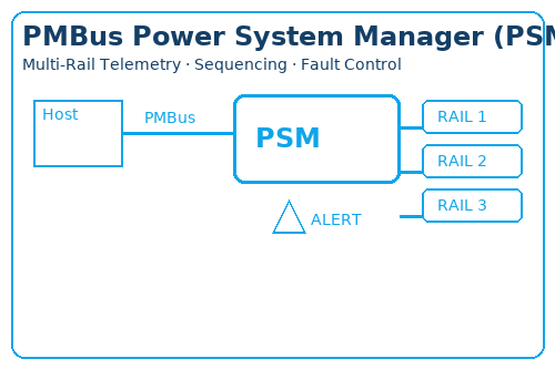
PMBus Power System Manager (PSM) — Multi-Rail Telemetry, Sequencing & Fault Control
What: A PMBus Power System Manager centralizes multi-rail power control—V/I/P/T telemetry, thresholds & hysteresis, power-up/down sequencing, margining, fault policy, and logging—stored as NVM profiles for repeatable production.
When: Choose PSM when rail count ≥ 4–6, boards share a backplane, and you need remote configuration plus traceable logs; it cuts bring-up time and maintenance versus scattered supervisors + discrete rails.
Outcome: Maintainability-first selection (accuracy, resolution, dependency depth, log capacity, command coverage, address plan) and ready-to-use tools—worksheet, command quick map, and a 48-hour BOM-to-options prescreen.
Section Anchors
Definition & Role
A PMBus Power System Manager (PSM) is a system-level, multi-rail controller that centralizes V/I/P/T telemetry, programmable thresholds & hysteresis, power-up/down sequencing, margining, fault policy, and event logging—all exposed through PMBus/SMBus commands and persisted as NVM profiles for repeatable production and field updates.
In practical terms, a PSM shortens bring-up by making limits, actions, and dependencies explicit, scriptable, and verifiable; it standardizes configuration across prototypes, pilot runs, and mass production via profile cloning; and it improves diagnosability & maintainability by turning rail behavior into queryable telemetry and audit-ready logs.
For backplane or multi-board systems, a PSM also coordinates rails and alerts across cards: sequencing dependencies, shared PG/ALERT signaling, and policy-driven fault responses reduce manual rework, field guesswork, and inconsistent fixes between units or revisions.
Adoption threshold. Choose a PSM when rail count ≥ 4–6, when remote configuration and traceable logs are required, or when boards share a backplane and must coordinate power-up/down behavior. Below these thresholds, lighter supervisors or simple sensing may suffice; this page focuses on system-level power management rather than basic regulator theory.
Scope note: this section defines the role and value of a PMBus-based system manager. It does not revisit fundamentals of PMICs, LDOs, or buck regulators—see the parent page if needed.
How PMBus PSM Works
Command layer
A PSM exposes a standardized command surface: read V/I/P/T and status, write thresholds & hysteresis, assert ON/OFF, apply margining, clear faults, and save/load NVM profiles. In practice, workflows are scripted: read baseline → batch-write limits & policies → verify by read-back → persist to a profile (with an ID or hash) so the same behavior is reproduced across prototypes and builds.
Event layer
Rail conditions map into PG/ALERT and status bits that the system routes as interrupts. A configurable policy table decides the response: shut down, retry after a cool-down, current-limit, or derate—optionally gated by dependencies and timing windows. Debounce, glitch filtering, and timeouts keep signaling stable on noisy or hot-swap backplanes.
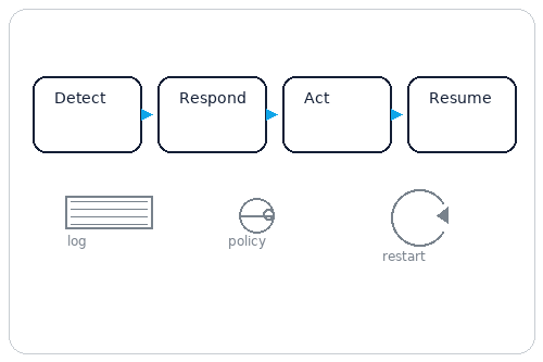
Closed loop
The manager executes a loop: measure → compare to thresholds (with hysteresis/margins) → trigger policy → log the event with timestamp/counters/context → host collects and archives → engineers tune thresholds/policies with evidence. “Black-box” logs and fault-injection enable reproducible diagnosis and continuous improvement.
Implementation notes
Prefer public PMBus commands for portability and wrap vendor extensions behind a thin abstraction so multi-vendor parts share the same scripts. Enforce a safe order— baseline → write → verify → persist → sign—and store configuration as files (CSV/JSON) for audit. Define a minimum command set and a degrade plan when certain opcodes are unavailable on specific devices.
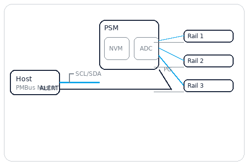
System Architecture — PMBus Host → PSM → Multi-Rail Power

A PMBus Power System Manager (PSM) sits between the host/controller and multiple power rails. Over PMBus (SMBus/I²C physical layer), the host reads voltage/current/power/temperature, writes thresholds and hysteresis, programs sequencing and margining, receives PG/ALERT events, and stores production profiles in on-chip NVM/EEPROM. The result is a closed loop: measure → compare → event → policy → action → verify → log.
A. Multi-Channel Measurements (V / I / P / T)
The PSM samples rail voltages and currents (and board temperature) and exposes them as registers for threshold comparison and telemetry. Key selectors include channel count, resolution/effective bits, and sampling rate (ms-level suffices for most power; fast transients require kS/s plus buffering). Plan the front-end carefully: divider values/tolerance and shunt sense paths with Kelvin routing, plus small RC filtering to tame switcher ripple. Total error is the root-sum of ADC error, reference error, front-end tolerance, and temperature drift. Don’t size thresholds solely from ADC specs—budget end-to-end.
B. Sequencing (Power-Up / Power-Down)
The PSM enforces ordered bring-up and bring-down using a dependency graph with per-rail delays, PG qualifiers, timeouts, and retry policies. Select adequate delay resolution (µs/ms) and max dependency depth. Add de-bounce on PG and allocate jitter margin around device timing windows. Down-sequencing must be explicit (often the reverse of up-sequence) to avoid back-powering peripherals. Log timeouts and retries for production triage.
C. Margining (±% Adjustment)
Margining nudges target voltage by ±% for factory calibration, aging studies, or derating. Check step size, range, and whether the path is DAC/reference injection or a digital parameter into the converter. Always verify by re-reading measured voltage before/after the change and commit the result to the event/log store. Avoid simultaneous margining of many rails on a weak upstream bus—transient droop can cause false trips elsewhere.
D. Fault / Alert (PG Aggregation & Event Propagation)
OV/UV/OCP/OT and PG-timeout conditions map to ALERT/interrupt lines and trigger policy actions (shut-down, retry, current limit, derate). Prefer partitioned ALERT domains for critical rails versus noisy rails to avoid storming. Provide pull-ups near the master, add RC de-bounce, and include ESD/transient protection at backplane connectors. Fault masks and priorities should be captured in versioned profiles for predictable behavior across SKUs.
E. NVM / EEPROM (Profiles & Calibration)
Configuration lives in one or more profiles with write protection, CRC/signature, and a readable version/commit hash. Production flows perform: write → verify → lock (if used) → export summary. To preserve endurance, write only the changed blocks and guard against brown-out during programming. Field updates must include a rollback path to a known-good profile.
F. Bus & Addressing (PMBus / SMBus / I²C)
Choose bus speed (100/400/1000 kHz) for expected polling bandwidth and number of devices. Maintain a centralized address map with spare slots for growth.
For backplanes, segment with bridges/isolators; place pull-ups near the master; limit stubs and consider series damping for long trunks.
As a quick estimate, select pull-ups from the rise-time budget: RPU ≈ trise / (0.847 × Cbus), balancing current and edge speed.
G. Closed-Loop & Data Flow
The operational loop is Measure → Compare → Event → Policy → Action → Verify → Log. Live data resides in readable registers/counters; durable policy and calibration are in NVM profiles. Host tools batch read/write with error codes and provide recovery and rollback routines for safe updates.
H. Typical Topologies
- Single board (8–16 rails): one PSM with local PG/ALERT aggregation; direct PMBus to host.
- Backplane/chassis: one PSM per board; ALERT domains rise to a supervisor on the main board; PMBus segmented via isolators/bridges.
- Hybrid: digital VR controller manages CPU/FPGA core rails; the PSM coordinates the remaining system rails and consolidates telemetry.
Need an address map & sequencing template? Get the PSM Selection Worksheet in Resources & RFQ.
Selection Guide — Decide, Quantify, and Prepare Your PSM Specs
TL;DR: Choose a PMBus Power System Manager when you have ≥6 rails, strict sequencing/dependency, and need telemetry, logging, and remote reconfiguration. If you only need PG/reset, see Supervisors & Watchdog. For multi-phase core rails, see Digital VR Controller.
Step 1 — Rail Inventory
Count rails (n), target V/I per rail, tolerance (±%), dependency graph (DAG), and power-up / power-down priority.
- When n ≥ 6 or dependency depth d ≥ 3, you benefit from programmable sequencing and fault policy.
- Enforce reverse-order power-down that mirrors the power-up dependencies.
Excel mapping: Sheet Rails → Name | Vtarget | Itarget | Tol(±%) | DependsOn | tON(ms) | Timeout(ms) | Retry(k) | PwrDownOrder.
Step 2 — Measurement Chain
Define accuracy (system-level, not just IC), sampling rate (ms-class vs. transient capture), and drift/TempCo.
- Total error ≈ sqrt(ADC² + reference² + sense-network²) + drift(T, time).
- Set hysteresis ≥ 3× RMS noise to avoid chatter; verify at temperature corners.
Excel mapping: Sheet Thresholds & Hyst → MeasAcc(%) | Noise(mV) | Hyst(mV) | TempCo(ppm/°C).
Step 3 — Sequencing & Policy
Choose timing resolution (µs/ms), max dependency depth, timeout/retry, and consistent power-down order.
- Allowed window Δt ≥ delay ± (resolution + jitter).
- Define fault actions per rail: shutdown, retry(k), margin/derate, or limit current.
Excel mapping: Sheet Rails + Command Map → tON/tOFF, Timeout, Policy.
Step 4 — Interfaces & Expansion
Size GPIO/PG/ALERT and check mapping flexibility. Plan bus speed, addressing, isolation, and host bandwidth.
- Bus speed: 100/400 kHz or 1 MHz; pull-ups placed near the master; avoid stubs on backplanes.
- Address plan for multi-board systems; aggregate ALERT with correct fan-out and pull-ups.
Excel mapping: Sheet Address & Bus → I²C Addr | Bus Speed | Pull-ups | Cable/Backplane | Isolation.
Step 5 — Maintenance & Compliance
Define NVM profile count, write-protection, version hash/rollback; confirm AEC-Q100 (if needed) and thermal limits.
- Track configuration hash across production and field—reject mismatches on service swaps.
- Verify TJ, θJA, derating, and physical footprint/thermal path.
Excel mapping: Meta + Sheet Thermal → Profiles | Lock | Version | θJA/Power.

| Field | Why it matters |
|---|---|
| Rail capacity | Scales with system size; drives dependency depth and timing budget. |
| V/I/P/T accuracy & rate | System-level limits for thresholds, alarms, and margin verification. |
| Threshold/hysteresis granularity | Determines alarm stability vs. noise; smaller steps = finer control. |
| Sequencing resolution/dependency depth | Meets tight windows; supports complex DAGs without race conditions. |
| GPIO/PG/ALERT count & mapping | Flexible fault routing and status aggregation across boards. |
| NVM size/profile count | Enables production vs. field profiles, rollback, and lock-down. |
| PMBus command coverage | Ensures your scripts can read/modify telemetry, thresholds, on/off, margin, and logs. |
| Bus speed/addressing | Throughput, collision avoidance, isolation strategy on backplanes. |
| Package & thermal | Board fit, θJA, and thermal path affect reliability under load. |
| AEC-Q100 (if applicable) | Automotive qualification and diagnostic coverage requirements. |
Score = Σ (weighti × normalize(parameteri, target)) — set weights per application (e.g., Server: accuracy 20%, sequencing 25%, interfaces 20%, maintenance 20%, thermal 15%). The Excel template lets you override weights.
Worked Example — 8-Rail Edge AI Board
- Dependencies depth = 4; two sensitive rails at 1.0 V / 1.8 V with tight windows.
- Timing: resolution ≥ 1 ms; define timeout and retry(k) per dependent cluster.
- Accuracy: total error target ≤ ±1.5% after combining ADC, reference, and sense tolerances.
- Address plan: main board×2 + mezzanine×1 with I²C isolation; aggregated ALERT.
Tip: import this scenario into the Excel worksheet to auto-compute weights and a ranked matrix.
Common Pitfalls to Avoid
- Using IC “typical accuracy” as system accuracy; ignore divider/shunt tolerances and TempCo.
- Specifying power-up only; missing reverse-order power-down alignment.
- PG/ALERT aggregation without fan-out and proper pull-ups → false faults/chatter.
- Address conflicts on multi-board backplanes; long-stub PMBus routing.
- No version/rollback control → field board swaps break configuration parity.
Implementation & Integration — From Schematic to Stable Bring-Up
Schematic Checklist
- Dividers/shunts: scale into 40–80% of ADC full-scale; combine tolerances (resistors, reference, TempCo) for system accuracy.
- Front-end RC: 10–100 Ω / 1–10 nF to tame spikes; avoid excessive delay that hides transients.
- Reference & grounds: 100 nF + 1 µF near Vref; analog↔digital grounds meet at a single point.
- Protection: low-cap TVS / RC damping for hot-plug/backplane surges.
Document tolerance math in the Excel Thresholds & Hyst sheet (hysteresis ≥ 3× noise RMS).
Layout & Cabling
- Route sense pairs tightly; minimize loop area; avoid running parallel to switching nodes.
- Place PMBus pull-ups at the master; avoid multi-point pull-ups on long backplanes.
- Use I²C isolators/buffers at chassis boundaries; match bus speed and rise-time budgets.
- Use shielded twisted pair on long runs; decouple chassis and signal grounds.
ALERT/PG Network
- Size pull-ups for total bus capacitance and target rise time; verify fan-out on aggregated ALERT.
- Add small RC de-glitch (e.g., 1–4.7 nF) to PG/ALERT if chatter occurs; avoid over-filtering.
- Series resistors (22–100 Ω) and TVS for off-board runs; buffer if load is heavy.

Address Plan & Command Abstraction
- Create a master table: Device | I²C Addr | Board | Slot | Spare; reserve forbidden/alias addresses.
- Abstract scripts: read telemetry, set thresholds/hysteresis, on/off, clear faults, export logs, switch profile.
- Validate profile state before enabling sequencing; enforce safe-write / lock after production.
Map details in Excel Address & Bus and Command Map sheets.
Calibration & NVM Governance
- Production: room-temp calibration + TempCo; write profile+cal into NVM and lock.
- Field: controlled re-calibration window; increment version and sign every change.
- Keep at least two NVM profiles (active/backup); allow rollback on anomalies.
- On power-up self-test, hash-check configuration; reject run if mismatch.
Scripted Bring-Up (text flow)
- Power On
- Load Profile
- Self-Test (I²C/PSM/NVM)
- Read Baseline Telemetry (V/I/T)
- Enable Monitoring & Alerts
- Start Sequencing
- Log Policy Active (fault map armed)
- Enter Steady State
Telemetry & Diagnostics — See, Log, and Improve
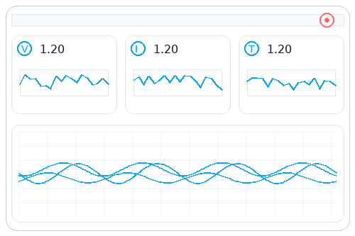
Realtime Telemetry
- Per-rail V/I/P/T, PG state, limit/margin status; choose polling vs. interrupt-driven updates.
- Track measurement noise, resolution, and TempCo; surface “effective digits” in the UI.
- Use pre-alarms (x% from threshold) for predictive maintenance.
Event & Fault Logging
- Minimum fields: timestamp, rail, type (OV/UV/OCP/OT/timeout), PG, dependency context, retry count.
- NVM ring buffer + host periodic fetch; overwrite oldest when full; export CSV/JSON.
- Capture snapshots for key events (last N samples + dependency states).
Diagnostics Workflow
- Read telemetry and logs
- Archive to central store
- Reproduce/Inject in the lab
- Root-cause analysis (RCA)
- Policy update (retry/derate/limit/hysteresis)
- Commit profile with version notes

Production ↔ Field Sync
- Production baseline: steady-state V/I/T, noise, PG rise time stored per SN.
- FAT/SAT: import configuration hash; fail if mismatched.
- Field swaps: power-up self-test blocks run until the correct profile is applied.
- Return path: periodic log uploads → review → batched policy updates to sites.
KPIs & Health Scores
- Per-rail |ΔV|/Vnom, ripple trend, peak temperature, faults per kHr, false alarm rate, avg resets/day.
- Define a Health Score (0–100) from deviation, false alarms, thermal headroom, and event density; auto-open maintenance tasks below threshold.
PSM vs Alternatives — Choose the Right Level of Power Management
PSM — PMBus Power System Manager
Multi-rail telemetry, sequencing/dependencies, fault policy, logging, and remote configuration. Scales across boards and chassis; supports NVM profiles and service workflows.
Supervisor
Lightweight / low-cost reset/PG monitoring. No system-level sequencing, no logs, no remote configuration. Best when requirements are simple and rail count is low.
Digital VR Controller
Focused on single critical rail (often multi-phase core) closed-loop control. Telemetry is rich but mostly for that rail; system-level coordination is limited.
PMIC
Highly integrated, compact solutions with selected rails on-chip. Flexibility and maintainability can be limited; cross-board orchestration is harder.
| Capability | PSM | Supervisor | Digital VR Ctrl | PMIC |
|---|---|---|---|---|
| Rail scale (system size) | ✅ Multi-rail / cross-board | — Few rails | ⚠ Single key rail | ⚠ Limited set on-chip |
| Telemetry depth (V/I/P/T, logs) | ✅ System-wide + logging | — Minimal | ⚠ Rich for one rail | ⚠ Varies by device |
| Sequencing & dependency | ✅ Programmable DAG + timing | — None | ⚠ Local only | ⚠ Basic / fixed |
| Policy & actions (retry/derate/limit) | ✅ Flexible per rail | — Reset only | ⚠ Rail-scoped | ⚠ Limited set |
| Remote config & NVM profiles | ✅ Yes (profiles, rollback) | — No | ⚠ Limited | ⚠ Device-specific |
| Integration scope (board ↔ chassis) | ✅ Board & backplane | — Single board | ⚠ Local domain | ⚠ Board-centric |
| Time-to-validate | ⚠ Medium–Long | ✅ Short | ⚠ Medium | ✅ Short–Medium |
| TCO impact (BOM vs. debug/maintenance) | ⚖ Balanced | Low BOM | Rail-focused | Low BOM |
Decision Checklist
- Need only PG/reset, no complex dependencies/logging/remote config → Supervisors & Watchdog.
- Single critical rail (multi-phase core) with tight loop control → Digital VR Controller.
- Max integration/small footprint, few rails, low complexity → PMIC.
- Rails ≥ 6 or dependency depth ≥ 3, need logging/remote config/cross-board coordination → PSM.
- Require fault policy + black box + field rollback → PSM.
When to Prefer PSM — Typical Scenarios
- Server/network/storage chassis with backplane coordination and hot-swap.
- Industrial/rail/energy with long I²C runs, EMI/transients, and policy-driven protection.
- Medical imaging with strict up/down sequencing and high cost of downtime.
- Automotive domain controllers requiring AEC-Q, profile integrity, and rollback.
Cost & Risk Notes
- Short-term BOM vs. long-term TCO: supervisors/PMICs may win BOM, but lack logs/remote config increases debug and field service costs.
- Validation time: PSM/VR need more validation; you gain diagnosability and maintainability.
- Portability: PSM profiles + scripts are reusable across SKUs and sites, reducing fragmentation.
Where to go next
- Only reset/PG → Supervisors & Watchdog
- CPU/FPGA multi-phase core → Digital VR Controller
- Integrated power solution → PMIC hub
- Stay here for system-level management → see Selection Guide & Resources
Reliability, EMI & Safety — Budget, Test, and Prove
Tolerance Budget — Thresholds & Hysteresis
Combine measurement chain, reference, sense network, load variation, and temperature.
Mini example: If total error is ±1.2% and RMS noise is 4 mV, set hysteresis ≥ 12 mV + load-step headroom.
Failure Modes & Effects
| Failure mode | Detection | Policy action | Log fields |
|---|---|---|---|
| OV/UV | Threshold + hysteresis; pre-alarms near margins | Shutdown / retry(k) / margin | Time, rail, V, policy, count |
| OCP/OT | Current/temperature thresholds; rate-of-rise | Limit current / derate / shutdown | Time, rail, I/T, policy, count |
| PG timeout | Timer per dependency stage | Retry(k) / abort sequence | Time, stage, timeout, retries |
| Loose cable / hot-plug spark | Debounce + transient counters | Hold-off / clamp / shutdown | Time, event type, duration |
| I²C arbitration failure | Status bits, NACK counters, timeouts | Bus reset / backoff / isolate | Time, address, op, error |
EMI & Long Cable Practices
- Compute pull-ups from total bus capacitance and target rise time; avoid multi-point pull-ups.
- Partition analog/digital grounds; route remote-sense pairs tightly; keep PG/ALERT away from switching nodes.
- Use bus buffers/isolators for chassis transitions; shielded twisted pair on long runs; consider common-mode chokes.
- TVS + series resistors for off-board lines; RC damping for hot-plug boundaries.
Functional Safety Notes
- De-correlate monitor vs. actuator paths (different devices/zones where feasible).
- Define a fail-safe action per critical rail (shutdown/limit/derate/hold) with timeouts.
- Self-test PG/ALERT loops; verify NVM integrity; supervise with watchdog.
| Rail | Condition | Action | Timeout | Rationale |
|---|---|---|---|---|
| Core 1.0 V | UV > 5 ms | Shutdown + retry | 500 ms | Protect logic integrity |
| I/O 1.8 V | OV > 2 ms | Derate / clamp | 200 ms | Avoid latch-up |
Verification & Fault Injection
- Read baseline (steady-state V/I/T, PG timings)
- Inject (pull up/down, overload, heat/cool, I²C collisions)
- Observe (telemetry, PG, logs)
- Verify policy (actions, timeouts, retries)
- Check persistence (logs complete & exportable)
- Report & fix (update profile; record version/rationale)
KPIs & Pass/Fail Criteria
- False-alarm rate ≤ X per kHr; fault capture ≥ Y%; MTTR trending ↓; |ΔV|/Vnom within spec; power sequencing success ≥ Z%.
- I²C error rate below target; ALERT/PG chatter count near zero with proper hysteresis/debounce.
- Define green/amber/red ranges per KPI in your validation plan.
Downloads: PMBus Command Quick Map (PDF) · Multi-Rail Bring-Up Checklist (PDF) | Submit your BOM (48h)
See also: Telemetry & Diagnostics · Implementation & Integration
Application Maps — What PSM Solves Across Industries
This section summarizes from the power system management viewpoint only—multi-rail coordination, PMBus telemetry, sequencing, and fault policy. It does not detail full power trees (see application pages for that).
Server / Switching / Storage (Chassis & Backplane)
Backplane multi-board coordination, cold/hot-swap, and closed-loop logging at rack scale.
Key challenges
- Cross-board dependency sequencing and PG/ALERT aggregation.
- Hot-plug transients and I²C arbitration across long busses.
- Fleet-level log traceability and profile rollback.
PSM value
- Programmable DAG sequencing, per-rail policies (retry/derate/limit/shutdown).
- Black-box logs with dependency context; NVM profiles for field rollback.
- Address/ALERT planning and unified scripts across sleds and blades.
Example part numbers
| Vendor | Family / PN | Notes |
|---|---|---|
| Analog Devices | LTC2977, LTC2978, LTC2974 | 8-/8-/4-rail PSM with PMBus, telemetry, sequencing |
| Texas Instruments | UCD90320, UCD90240, UCD90120A | 32-/24-/12-rail power sequencer/monitor with PMBus |
PNs are indicative for PSM-class devices; validate final specs in Selection Guide & RFQ.
Industrial Control / Factory Automation
Long I²C runs, harsh EMI/ESD, and offline maintenance windows.
Key challenges
- ESD/surge, common-mode noise, and intermittent connectors.
- Bus recovery, isolation, and debounced ALERT/PG networks.
- Spare board configuration parity across sites.
PSM value
- Robust long-bus design (pull-up sizing, buffering/isolators, hysteresis/debounce).
- Forensics-ready logs and baseline telemetry for rapid root cause.
- Profile hash check to guarantee replacement-board consistency.
Example part numbers
| Vendor | Family / PN | Notes |
|---|---|---|
| Analog Devices | LTC2975, LTC2977 | Quad/Octal PSM; logging and margining over PMBus |
| Texas Instruments | UCD90160A, UCD90320 | 16-/32-rail PMBus sequencer & monitor |
Choose isolators/buffers per cable length and rise-time budget; see Implementation section.
Medical Imaging
Tight sequencing windows, thermal/noise constraints, and audit-grade traceability.
Key challenges
- µs/ms-class up/down windows with strict dependency ordering.
- Thermal and noise coupling across modules.
- Evidence retention for compliance and service.
PSM value
- Fine sequencing resolution and per-rail fail-safe policies.
- Detailed logs (incl. dependency context, counters, timestamps).
- Pre-alarm thresholds for predictive maintenance.
Example part numbers
| Vendor | Family / PN | Notes |
|---|---|---|
| Analog Devices | LTC2978, LTC2974 | Octal/quad PSM; fine timing, telemetry, fault logging |
| Texas Instruments | UCD90120A, UCD90240 | 12-/24-rail PMBus sequencer/monitor |
Validate sequencing resolution and jitter vs. your allowed window before design freeze.
Automotive Domain Controller / Gateway
AEC-Q needs, brown-outs, and clearly defined safe states.
Key challenges
- Cold-crank / voltage dips and wide temperature ranges.
- Diagnostics coverage and safe-state definition per rail.
- Lifecycle governance (development ↔ production ↔ service profiles).
PSM value
- Multiple NVM profiles with version control and rollback.
- PG/ALERT self-checks, NVM integrity verification, watchdog supervision.
- Policy actions: shutdown/limit/derate with timeouts for fail-safe.
Example part numbers
| Vendor | Family / PN | Notes |
|---|---|---|
| Analog Devices | LTC2977 (check AEC-Q variants) | Octal PSM; confirm temperature grade and qual status |
| Texas Instruments | UCD90xxx family | Confirm AEC-Q100 availability per device |
Automotive use requires explicit confirmation of AEC-Q grade, diagnostics, and safe-state timing.
Continue with: Selection Guide · Implementation & Integration · Telemetry & Diagnostics
Notes: Part numbers are provided as illustrative PSM-class examples. Always validate features, timing resolution, PMBus command coverage, and environmental/qualification requirements against your project’s MVS in the worksheet before RFQ.
FAQs
Quick, engineering-oriented answers. Each item links to the relevant section for deeper guidance.
How does PMBus relate to SMBus/I²C?
PMBus is a power-management command set layered on SMBus, which in turn uses the I²C physical layer. PMBus standardizes commands for telemetry, thresholds, on/off, margining, and logging, while vendors may add extensions. Treat PMBus as an application-level protocol running over SMBus/I²C. See: Definition.
When does a project benefit from a PSM?
Adopt a PSM when you have ≥6 rails, dependency depth ≥3, cross-board coordination, or a need for field logging and remote configuration. Otherwise, supervisors or compact PMICs may suffice for simple PG/reset needs. See the decision flow and weights in: Selection Guide and Comparison.
How do I compute thresholds and hysteresis with tolerances?
Combine ADC, reference, and sense-network errors (RSS), then add drift: ε_sys ≈ √(ε_ADC²+ε_ref²+ε_sense²)+drift(T,t). Set thresholds from V_nom·(1±margin) and choose hysteresis ≥ 3×RMS noise plus load-step headroom to prevent chatter. Document math in your worksheet. See: Reliability and Selection Guide.
Which timing windows are impacted by sequencing resolution?
Resolution and jitter impact power-up/down order, PG timeouts, inter-rail dependencies, and retry spacing. Your allowed window should exceed delay ± (resolution + jitter) to avoid races. Validate at temperature corners and under load transients. See: Selection Guide and Implementation.
Margining vs. production calibration—what’s the difference?
Margining temporarily biases rails (±%) to verify system tolerance and policy behavior. Calibration improves measurement accuracy (offset/gain/TempCo) and is committed to NVM for life-cycle consistency. Margining tests robustness; calibration ensures truthful telemetry and thresholds. See: Implementation and Telemetry.
Do black-box logs survive power loss?
Typically yes—PSM devices store events in NVM or a ring buffer periodically flushed to NVM. Capacity is finite; oldest entries are overwritten. Schedule regular exports during service windows to preserve evidence. Confirm device-specific retention behavior. See: Telemetry & Diagnostics.
How do I prevent address conflicts on backplanes/multi-board systems?
Maintain a master address table, reserve forbidden ranges, and partition buses with isolators where needed. Place pull-ups near the master, avoid multi-point pull-ups, and design ALERT aggregation with proper fan-out and filtering. Verify at system level. See: Implementation.
How to stabilize long I²C lines and mitigate EMI?
Size pull-ups from total bus capacitance and target rise time; use buffers/isolators at chassis boundaries; route remote-sense pairs tightly; use shielded twisted pair and, if needed, common-mode chokes. Add RC de-glitch on PG/ALERT. Avoid running near switching nodes. See: Reliability and Implementation.
How does a PSM coordinate with a digital VR controller?
The VR controller closes the control loop for a critical rail (often multi-phase core). The PSM orchestrates system-level sequencing, policies, and logging across rails and boards via PMBus/PG/ALERT. Keep roles distinct and interfaces explicit. See: Comparison and Implementation.
What diagnostics matter for AEC-Q100/automotive programs?
Plan PG/ALERT loop self-tests, NVM integrity checks, watchdog supervision, and clearly defined fail-safe actions with timing. Validate across temperature extremes, brown-outs, and cold-crank conditions. Track configuration hash for profile parity. See: Applications and Reliability.
How should I version and roll back NVM profiles?
Keep at least two profiles (active/backup). Increment version, record a signed hash and rationale for every change, and verify the hash at power-up. Support atomic switch-over and rollback on anomalies. Gate sequencing until integrity passes. See: Implementation and Telemetry.
What if telemetry bandwidth is limited?
Promote critical metrics to interrupt-driven events, reduce polling frequency for noncritical rails, and downsample or bucketize numeric streams. Add pre-alarms near thresholds to anticipate faults. Periodically export logs for offline analysis. See: Telemetry & Diagnostics.
What’s the safe order for batch write/read from the host?
Load profile → verify → lock → capture baseline telemetry → enable monitoring → start sequencing. On reads, verify configuration hash and signatures before trusting data. Use timeouts/backoff and idempotent scripts for reliability. See: Implementation and Resources.
Risks when updating configuration online?
Power loss, arbitration failures, or partial writes can leave devices inconsistent. Use a shadow area, verify integrity, then perform an atomic switch; keep a backup profile for instant rollback. Quiesce sensitive rails if needed. See: Implementation and Reliability.
What is the minimal acceptance test set for production/field?
Verify up/down sequencing, OV/UV/OCP/OT injections, PG timeout behavior, I²C error recovery, log completeness/export, and health-score thresholds. Record pass/fail with configuration hash and profile version. Automate wherever possible. See: Telemetry and Reliability.
Downloads: PSM Selection Worksheet (Excel) · PMBus Command Quick Map (PDF) · Multi-Rail Bring-Up Checklist (PDF) | Submit your BOM (48h)
See also: Selection Guide · Implementation & Integration · Telemetry & Diagnostics · Reliability, EMI & Safety
Resources & RFQ
Download the minimum closed-loop toolkit. Each file is concise and editable—keep detailed tables and command maps in attachments to avoid cluttering the main page.
PSM Selection Worksheet (Excel) XLSX
Editable workbook to capture rails, thresholds/hysteresis, dependencies/timing, timeouts/retry, and address/command mapping. Includes a right-side Gantt-like timeline with two zoom modes.
- Sheets: Rails · Thresholds & Hyst · Address & Bus · Command Map
- Timeline: toggle 0–500 ms ↔ 0–5 s
- Weights: presets for Server/Industrial/Auto
PMBus Command Quick Map (PDF) PDF
Compact command-family map for telemetry, thresholds, on/off, margining, and logs, plus read/write timing diagrams. No vendor-private commands. Includes common ordering mistakes to avoid.
- Sections: Telemetry · Thresholds · On/Off · Margin · Logs
- Diagrams: SMBus/I²C read/write sequences
- Mapping: cross-ref to Worksheet fields
Multi-Rail Bring-Up Checklist (PDF) PDF
Printable 30+ item checklist for lab and field acceptance. Includes signature/date/version/board-ID and configuration-hash fields to preserve evidence and traceability.
- Coverage: sequencing, OV/UV/OCP/OT injections, PG timeout, I²C recovery
- Artifacts: log export, profile hash, rollback drill
- Sign-off: sign/date/version/board/config-hash
Submit your BOM (48h)
Get a parts short-list based on your rail count, dependency depth, accuracy, sequencing resolution, bus plan, and compliance needs.
Start RFQAttach your Worksheet and any timing screenshots for faster turnaround.
Request 3 pin-compatible options
Receive three alternatives with similar pins and features (no pricing). Useful for risk mitigation and second-source planning.
Request OptionsCompare related categories: Sequencer · Supervisors · Digital VR Controller · Voltage/Current/Power Sense · eFuse