
Multi-Rail System PMIC — From Rail Mapping to Safe Bring-Up
Preface: Multi-Rail System PMIC Page Intro
This page focuses on system-level multi-rail PMICs: centralized power for platforms such as SoC/FPGA/MPU/AI SoC with 3+ rails, covering power-up sequencing/tracking, DVFS, telemetry/faults, and PGOOD matrix. It targets prototyping and small-batch teams aiming to complete power-tree decisions and sourcing feasibility within 48 hours.
Device-level details are out of scope here — see dedicated subpages for LDO, stand-alone Buck, eFuse/Load-Switch, Supervisor, and PMBus register details. This keeps content unique across the 40+ subpages.
What Is a Multi-Rail System PMIC?
A system-level multi-rail PMIC is an integrated power manager that supervises 3+ interdependent rails with configurable power-up sequencing/tracking, DVFS, telemetry & fault handling, and PGOOD orchestration for SoC/FPGA/MPU/AI-SoC power trees.
When a System PMIC Fits
- 3+ interdependent rails with strict power-up order or tracking requirements.
- Need software control (I²C/PMBus) for DVFS, bring-up, or production test.
- Centralized sequencing/PGOOD/fault handling to cut area and validation effort.
- Board height/placement constraints; prefer unified thermal/EMI risk control.
When Discrete Wins
- Very few or widely scattered rails with loose dependencies.
- Special topologies or extreme specs (ultra-wide VIN, ultra-low noise/ripple, very high current).
- Need minimal change to an existing power tree with targeted swaps.
Device-level details are covered elsewhere to keep this page system-focused: last-stage noise with LDOs, and core high-current delivery with stand-alone Bucks.
How It Works — System PMIC Control Loop
The diagram below shows how a system-level multi-rail PMIC centralizes control from first power-up to safe shutdown: regulators are coordinated by a sequencing/tracking engine, run-time voltage states are managed via PMBus/I²C (DVFS), and telemetry + fault manager drive PGOOD/GPIO broadcasts.
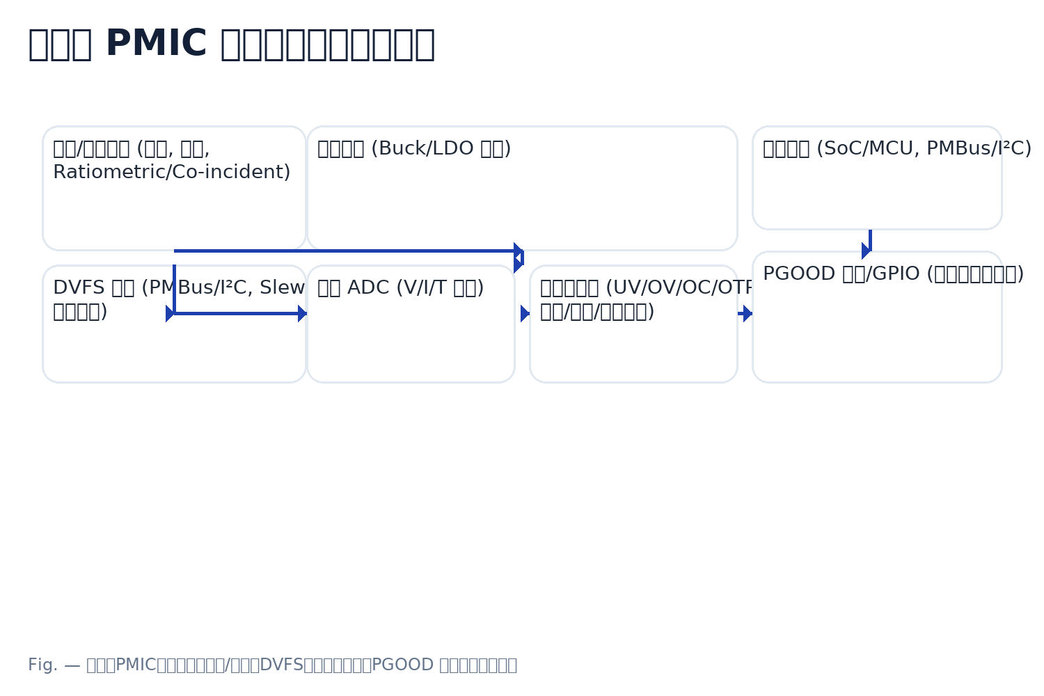
Start-up path. Rails are grouped with delays and a chosen tracking mode (ratiometric/coincident). PGOOD is released only after thresholds are met to avoid back-powering and latch-ups. Continue to Sequencing & Tracking.
Run-time path (DVFS). The host adjusts target voltages over PMBus/I²C. Transitions follow defined slew limits and stability windows while guarding UV/OV events. Continue to DVFS.
Monitoring & actions. Telemetry samples V/I/T continuously; the fault manager decides latch/retry/ordered shutdown and broadcasts status via PGOOD/GPIO. Continue to Telemetry & Faults.
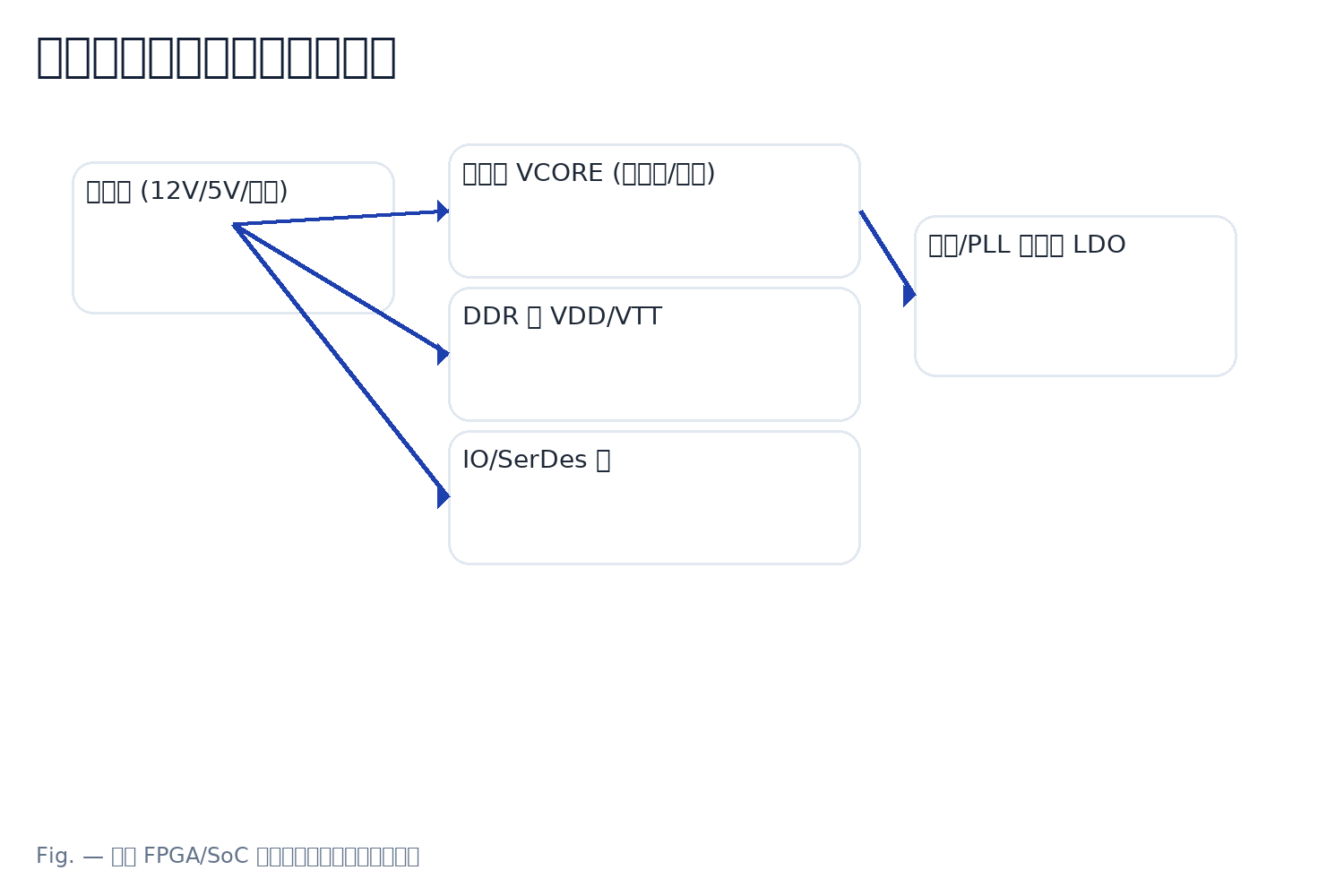
Power-Tree Planning — Rail Mapping & Budgets
Before defining sequences, map the power tree. A complete rail table becomes the single source of truth that drives grouping, priorities, tracking modes, DVFS limits, and verification scope.
Minimum Rail Table (fields)
- Name (rail label) • Voltage & Tolerance
- Steady / Peak Current • Ripple & Transient Margin
- Owning Block (Core / DDR / PLL / SerDes / IO / Analog)
- Priority (A/B/C…) • Group (for start-up batching)
With fields filled, you can derive delays, tracking pairs, and early PGOOD dependencies.
Engineering Notes
- Capture dependencies across Core/DDR/PLL/SerDes/IO; priority + grouping will drive start-up order and tracking.
- Identify cross-sensitivity early (e.g., analog rails near switching noise) — late fixes are costly in layout and validation.
- Keep DVFS candidates explicit; some rails must remain fixed to protect timing margins or low-noise domains.
For last-stage noise, see LDO. For core high-current or multi-phase options, see Buck.
Start-Up Sequencing & Tracking
With groups and priorities defined, choose a start-up strategy—serial, grouped, or parallel with delays—and a tracking mode—ratiometric or coincident. These decisions translate your rail map into an executable sequence.
Serial Start-Up
Safest dependency control; each rail (or group) enables after the previous one is stable and PGOOD is asserted.
Pros: predictable, simple PGOOD gating · Cons: longest boot time, possible cold-start droop accumulation
Grouped Start-Up
Common in SoC/FPGA: rails within a group power together; groups are separated by delays driven by priorities.
Pros: good balance of speed/control · Cons: validate in-rush per group and inter-group dependencies
Parallel + Delays
Fastest overall: multiple rails or groups start in parallel with carefully chosen delays to respect dependencies.
Pros: minimal boot time · Cons: tighter validation of in-rush, cross-domain effects, and brown-out margins
Ratiometric Tracking
Rails ramp together with proportional voltages, maintaining relative bias during the rise.
- Use for domains that must keep bias relationships (e.g., analog + reference).
- Pair with shared timing constraints to avoid transient mis-bias.
Coincident Tracking
Rails reach their targets at the same time with matched slopes (same dV/dt).
- Helps DDR/IO timing alignment and prevents false resets in digital domains.
- Rule of thumb: keep coupled domains on the same slope; otherwise isolate and gate.
Engineering Notes
- PGOOD matrix defines release order; enforce min/max delay windows.
- Guard against back-powering when IO precedes core; gate/reset accordingly.
- Synchronize multiple PMICs or companion bucks (shared CLK/EN) to avoid race conditions.
- DDR pre-conditions and slope consistency often require coincident tracking.
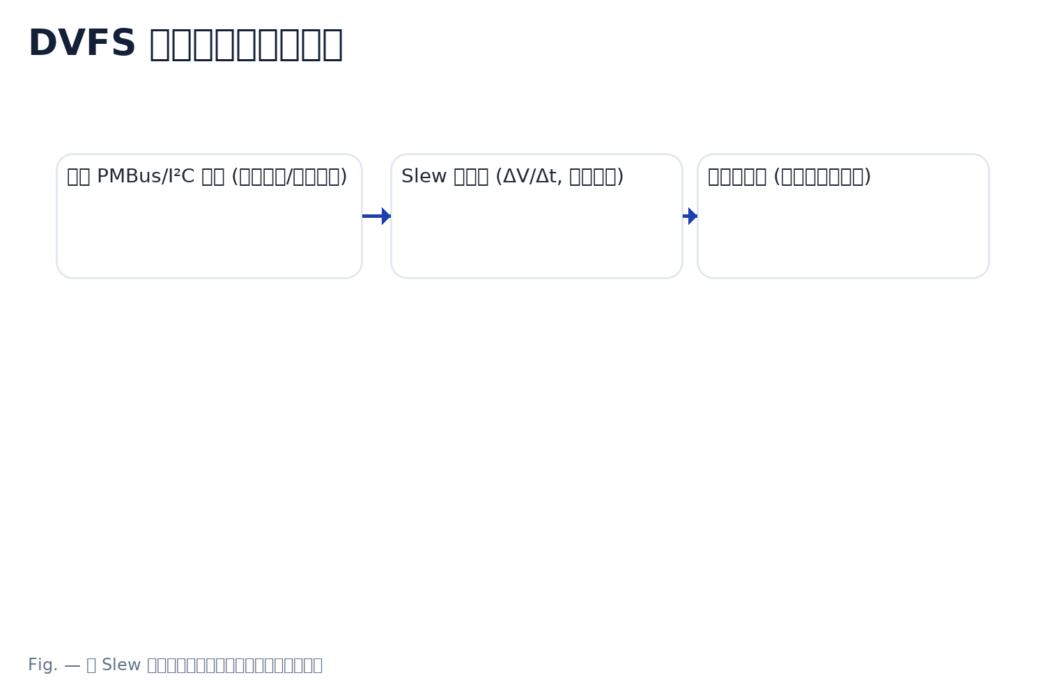
DVFS & Dynamic Rail Control
DVFS lets the host adjust rail setpoints and operating states at run time. Each change must respect defined slew limits and remain within a stability window, while alarms protect against UV/OV events.
Control — PMBus / I²C
Write target voltage/state, margin high/low, enable/disable, and poll status/alarms. Keep transactions short and predictable during critical loads.
- Setpoints & P-states table (CPU/GPU/SerDes mapping).
- Operational modes (enable, soft-start, margining).
- Status words and sticky fault reads for diagnostics.
Need command details? See PMBus / I²C Control.
Slew & Stability Policy
Constrain ∆V/∆t; enforce minimum dwell time at each step; verify loop compensation keeps the rail inside its stability window throughout the ramp.
- Match ramp slope for coupled domains to avoid bias skew.
- Validate step responses at worst-case load & temperature.
- Guard rails that must remain fixed (refs/PLLs/analog).
Alarm Thresholds
Set UV/OV thresholds with debounce/filtering; route to the fault manager (latch/retry/ordered shutdown) and log with timestamps.
- Under/Over-voltage limits with hysteresis or averaging.
- Transient masks for planned DVFS steps.
- PGOOD behavior during margin/transition periods.
Engineering Notes
- Map CPU/GPU/SerDes P-states to voltage table; lock non-negotiable rails.
- On step changes, guard against transient UV/OV with proper debounce and stability checks.
- Maintain domain isolation for analog/PLL/reference rails to contain digital switching noise.
- Balance telemetry resolution and sample rate with bus bandwidth & firmware budget.
Load Transient, Stability & Compensation
Transient quality depends on ΔI, loop bandwidth & phase margin, and the capacitor matrix (bulk + MLCC) operating within a safe ESR window. Use the recipe below to size parts and set expectations before validation.
Minimal Executable Recipe
- Target ΔI — derive from worst-case load step & duty cycle; include DVFS step sizes.
- Loop BW & PM — bandwidth to meet recovery time with ≥45–60° phase margin across PVT.
- Capacitor Matrix — bulk (energy) + MLCC (HF) sized for droop/ripple at ΔI.
- ESR Window — damping without peaking; avoid LC/ESR-zero misplacement.
Device-level compensation math lives in Buck/LDO pages; keep this section system-level.
Engineering Notes
- MLCC derating: account for bias & temperature (use 60–70% effective C for worst-case).
- Sense routing: keep away from SW/CLK nodes; use Kelvin sense where available.
- Thermal derating & returns: plan copper/vias; control return paths to reduce ground bounce.
- Domain isolation for analog/PLL/reference vs noisy digital rails.
Validation Checklist
- At worst temperature × max ΔI: measure droop/overshoot and recovery time.
- Verify DVFS steps remain inside the stability window and respect slew limits.
- Log PGOOD, alarms, and telemetry timestamps for correlation.
- Repeat with realistic in-rush and board-level parasitics (cables, harness, backplane).
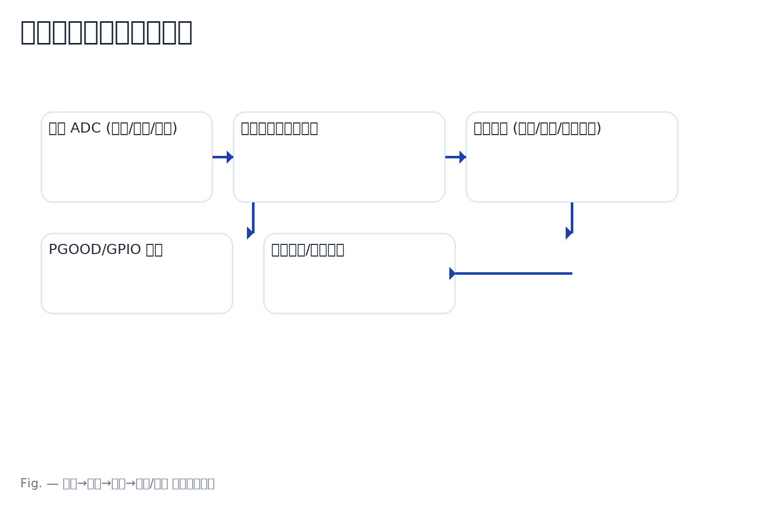
Telemetry, Protections & Fault Response
Telemetry turns rails into measurable signals (V/I/T). Pick a resolution and sampling rate the bus and firmware can sustain, and log events with timestamps so faults can be correlated and reproduced.
Monitoring Policy
Balance resolution and sampling rate against bus bandwidth and firmware budget.
- Choose ADC LSB and sample rate; use averaging or windowed filters.
- Throttle reads during DVFS steps to avoid I²C/PMBus congestion.
- Define per-rail log granularity (V/I/T, rate, and conditions).
Keep critical rails always-on for alarms; poll others opportunistically.
Fault Policy (UV/OV/OC/OTP)
For each rail, decide latch, auto-retry, or ordered shutdown with timers and limits.
- Severity- and state-aware policies (bring-up vs run-time).
- Retry back-off and maximum attempts to avoid oscillation.
- Coordinate with DVFS masks during planned transients.
Tie policy outputs into the fault manager and system supervisor/reset tree.
PGOOD & Field Diagnostics
Build a simple PGOOD fault tree; prefer a “degrade-first” posture before shutdown when safe.
- Gate or shed non-critical loads to stabilize core rails.
- Expose status via PGOOD/GPIO for downstream consumers.
- Provide a repeatable repro path for field → lab returns.
Use consistent semantics for PGOOD de-assert vs alarm active.
Logging & Snapshots
- Record timestamps, status words, rail V/I/T, retry counters, and the last N events.
- Capture register snapshots on first fault; include PMBus status pages.
- Correlate logs with scope captures for droop/overshoot/recovery.
- Persist a rolling buffer to aid return-to-lab analysis.
Layout & EMI for Multi-Rail PMICs
Layout is the foundation for stability and EMI. Minimize hot loops, plan return paths, isolate analog domains, and coordinate switching so compensation and DVFS behave as intended.
Power Stage & Hot Loops
Place input bypass capacitors tight to the power stage; shrink high-di/dt loops and keep SW nodes compact.
- Shortest VIN–SW–GND current loop; minimize loop area.
- Place CIN (HF) close; add bulk near load for energy.
- Via fences to stitch grounds around switching islands.
Return Paths & Ground Bounce
Give every high-frequency current a nearby return; avoid crossing plane splits and narrow necks.
- Low-impedance stitching near source/sink pairs.
- Avoid signals traversing reference plane gaps.
- Contain high-di/dt returns to local copper regions.
Sync / Spread-Spectrum & Proximity
Use clock sync or spread-spectrum to de-correlate energy; stagger phases in multi-rail switching.
- Keep adjacent SW nodes physically separated.
- Orthogonal routing and guard copper where needed.
- Mind beat frequencies vs system clocks/SerDes.
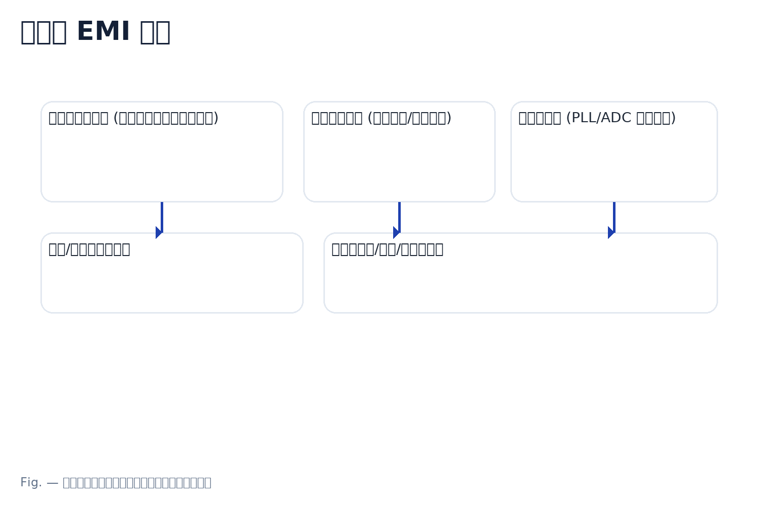
Analog-Domain Isolation
Protect PLL/ADC/reference rails from digital noise; route sense/Kelvin lines away from SW/CLK.
- Differential sensing or shielded corridors for sensors.
- Dedicated analog ground islands with single-point tie.
- Keep fast edges out of analog keep-out zones.
Thermal & Stackup
Spread heat with copper and thermal vias; plan A/B-side placement and height limits with package data.
- Heatspreaders and via arrays under hot devices.
- Respect keep-out for tall inductors and shields.
- Align stackup to controlled return and impedance goals.
Coordinate with enclosure airflow and neighboring heat sources.
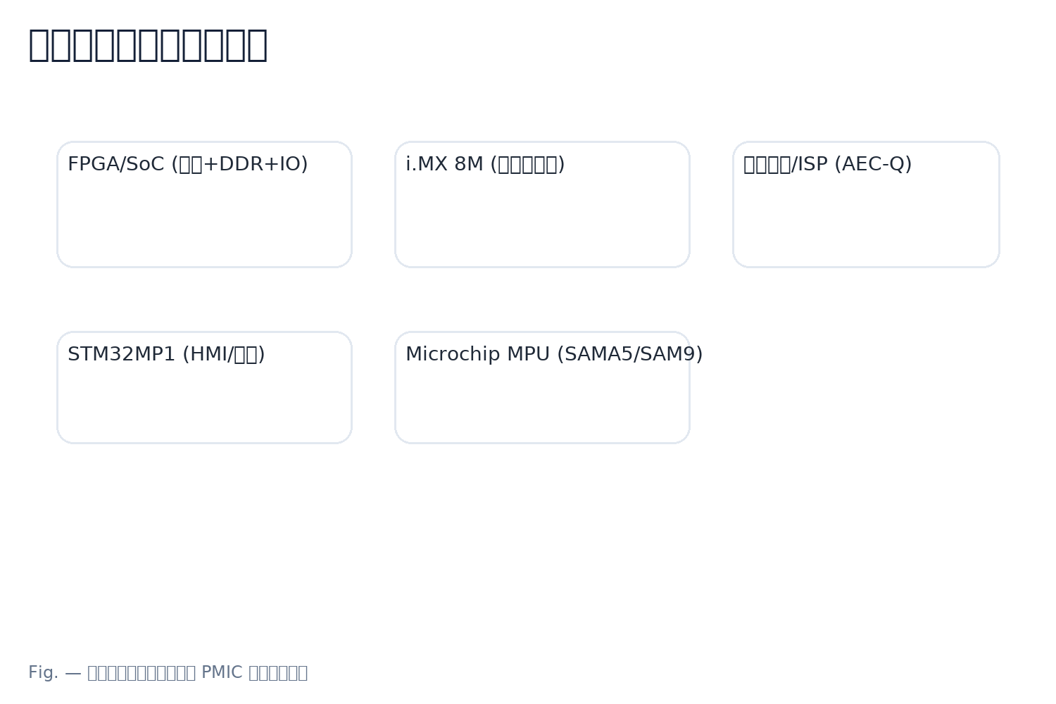
Applications & Brand Picks
Start with the application, then land on a system-level PMIC family and part number. Below are representative picks (1–2 per brand) that map well to typical multi-rail platforms. Device-level LDO/Buck details are intentionally out-of-scope here.
A — FPGA/SoC (Zynq/MPSoC with DDR/SerDes/IO)
- TI TPS650864 — ecosystem-aligned for Xilinx bring-up and sequencing.
- TI TPS65219 — general-purpose multi-rail controller for varied SoC mixes.
- Renesas RAA215300 — ~9 rails; DDR-friendly resources and PGOOD matrix.
- NXP PF8100 / PF8121 — ~7–12 rails; often used across i.MX & generic SoC boards.
- Microchip MCP16502 — 4×1A bucks + 2 LDO with I²C timing control.
- ST STPMIC1 — from STM32MP1 ecosystem; applicable to general SoC power trees.
- onsemi NCP6924 — ~6 channels; useful for auxiliary rails.
- Melexis — no system-level PMIC at present (note only).
Pick based on rail count/mix, PGOOD/telemetry needs, and board height/thermal constraints.
B — i.MX 8M Edge Multimedia
- NXP PCA9450 — tailored for i.MX 8M platforms.
- TI TPS65219 — flexible substitute when constraints differ.
- Microchip MCP16502 — compact rail mix for peripheral-rich boards.
Confirm DDR/IO slopes match your sequencing and tracking policy.
C — Automotive Camera / ISP (AEC-Q)
- Renesas ISL78083 — automotive-qualified, ISP and sensor rails.
- TI TPS65219-Q1 — AEC-Q variant for multi-rail camera subsystems.
- onsemi NCP6924 — auxiliary rails; pair with AEC-Q buck for core current.
Validate cold-crank/ load-dump protections and ordered shutdown behavior.
D — STM32MP1 (HMI / Gateway)
- ST STPMIC1 — native ecosystem fit with sequenced rails.
- TI TPS65219 — general multi-rail alternative for custom stacks.
- Renesas RAA215300 — richer rail counts for feature-heavy designs.
Check analog domain isolation for PLL/ADC rails vs digital switching islands.
E — Microchip MPU (SAMA5 / SAM9)
- Microchip MCP16502 — common choice for compact MPU platforms.
- TI TPS65217 family — historically used in similar MPU power trees.
Re-use proven rail maps to shorten bring-up and validation.
Selection Guide — Decision Matrix
Use this matrix to hard-filter by rail resources, sequencing, and mechanics, then soft-compare efficiency/thermal, telemetry granularity, and debug convenience. Fill it once and you should converge to three candidates with clear risks and alternates.
A. Rails & Types
- Rail count (total) · Types (Buck/LDO/DDR/Bias/Analog)
- Per-rail current (steady/peak) & efficiency curve
- Phase interleaving/paralleling capability
B. Sequencing & Gating
- Start-up resources (min/max delay, stages)
- Tracking modes (ratiometric / coincident)
- PGOOD matrix (programmability / width)
- External EN / GPIO availability
C. Control & Runtime
- I²C / PMBus (pages/commands coverage)
- DVFS granularity (step, slew/stability configurability)
- Telemetry resolution & max reporting rate (V/I/T)
D. Protections & Logging
- UV/OV/OC/OTP thresholds range
- Policies: latch / auto-retry / ordered shutdown
- Logging granularity (timestamps, snapshots, counters)
E. Package & Thermal
- Package code & footprint (pin pitch)
- Height limit (≤ mm)
- ΘJA / ΘJC (thermal resistance)
F. Qualification
- AEC-Q (Yes/No, grade)
- Temp range (-40…85/105/125 °C)
- Lifecycle / NRND
Step 1 — Hard Filter (one-strike kill)
Eliminate parts that fail any Rail count, Tracking support, Package/Height, or AEC-Q requirement.
Rows that fail are kept (grayed) with the failure reason for audit.
Step 2 — Soft Compare
Score 1–5 across: efficiency/thermal, telemetry granularity, debug convenience, DVFS flexibility, PGOOD/gating programmability.
Weights optional (default equal). Aim for evidence-based notes.
Step 3 — Output
Report Top 3 with key deltas. Add Risk | Alternate (impact) notes per candidate and proceed to procurement.
| Candidate | Rails / Types | Current / Eff. | Phases | Seq. Res. | Tracking | PGOOD | Ext EN | Bus | DVFS | Telemetry | Protection | Logging | Pkg | Height | ΘJA/ΘJC | AEC-Q | Env/Lifecycle | Hard Filter | Score (1–5) | Notes (Risk | Alt) |
|---|---|---|---|---|---|---|---|---|---|---|---|---|---|---|---|---|---|---|---|---|
| Vendor A / Part X | 9 rails · Buck/LDO/DDR | Up to 6A; 90%@2A | 2-phase parallel | 0.5–20 ms; 3 stages | Ratiometric & Coincident | 8× prog matrix | 4× EN / 2× GPIO | PMBus p1–p2 | 10 mV step; slew cfg | 1–2 mV; up to 2 kS/s | Latch/Retry/OSH | Timestamps + Snapshots | QFN 8×8 | ≤ 1.2 mm | 35/4 °C/W | Yes (Q1) | -40…105 °C; Active | PASS | 5 | Risk: height margin small | Alt: Part Y (re-route sense) |
| Vendor B / Part Y | 7 rails · Buck/LDO | Up to 4A; 88%@2A | Interleave only | 1–15 ms; 2 stages | Coincident only | 6× matrix | 2× EN / 2× GPIO | I²C only | 12.5 mV step | 2–4 mV; 1 kS/s | Latch/Retry | Timestamps | QFN 7×7 | ≤ 1.0 mm | 40/6 °C/W | No | -40…85 °C; Active | PASS | 4 | Risk: no PMBus | Alt: Part X (higher rail count) |
| Vendor C / Part Z | 6 rails · Buck | Up to 3A; 86%@2A | No parallel | Fixed delays | None | PGOOD 2× only | 1× EN | I²C | 25 mV step | 5 mV; 200 S/s | Latch only | None | QFN 5×5 | ≤ 0.9 mm | 50/8 °C/W | No | -40…85 °C; NRND | FAIL | — | Reason: no tracking/PGOOD width | Alt: Part Y (requires BOM change) |
Tip: keep failed rows for auditability; they explain why certain families were excluded.
BOM & Procurement — Prototype & Small-Batch Friendly
Send one concise package; within 48 hours you’ll receive three viable system-PMIC options ready for prototype or small-batch builds. This lane is strictly for system-level multi-rail PMICs.
You provide
- Rail table: Voltage, tolerance, I steady current/ peak currentpeak, ripple, ΔI.
- Grouping & start-up sequence: delays, tracking mode, PGOOD dependencies.
- Alarm thresholds: UV/OV/OC/OTP with debounce/masks.
- Mechanical limits: board thickness, max height (keepouts if any).
- Qualification: AEC-Q required? (Yes/No).
Attach files or link to docs; screenshots are fine as long as values are readable.
We return (≤48h)
- Three candidates: pin-to-pin, or function-closest when pin-compatible is impractical.
- Lead-time snapshot: region/distributor mix and near-term availability.
- Sample / cut-tape / small-batch feasibility and MOQs.
- Compliance documents: RoHS / REACH / AEC-Q (if applicable).
Notes will include risks/alternates and any layout/height caveats observed.
We do not collect extra personal data here; the centralized form on the PMIC hub is the single place where fields are maintained and updated site-wide.
Resources & RFQ
One hub for all templates used across this page, plus a single RFQ lane. Files here are the source of truth—grab the latest from this list.
Rail Sequencing Worksheet (PDF)
Input groups, order, delays, and the PGOOD matrix to define start-up sequencing and tracking policy.
FPGA/SoC Power Tree Checklist (PDF)
Consolidated checks: electrical budgets, transients, thermal, redundancy, DFM—use before tape-out.
PMBus Quick-Command Map (PDF)
Common commands and status words for bring-up; pairs with the DVFS and telemetry sections.
Thermal Budget Mini-Calculator (XLSX)
Rough ΔT estimate from efficiency η, output current Iout, and thermal resistance θJA.
Decision Matrix (CSV) · HTML
Templates used in §10 to hard-filter and soft-compare candidates, converging to a Top-3 list.
FAQs
Twelve focused answers. Click to expand each item; a single deep link at the bottom takes you to the full section.
SelectionWhen should I choose a system PMIC over discrete bucks+LDOs?
When should I choose a system PMIC over discrete bucks+LDOs?
Choose a system PMIC for three or more interdependent rails, strict sequencing/tracking, software DVFS control, and centralized PGOOD/fault handling to cut area and validation effort. Prefer discrete only for very few or scattered rails, extreme specs, or minimal-change retrofits.
SelectionWhat inputs do I need before shortlisting parts?
What inputs do I need before shortlisting parts?
Prepare a rail table: voltage, tolerance, steady/peak current, ripple, transient margin, owning block, priority, and grouping. This drives sequencing/tracking and narrows families early, avoiding late layout/EMI rework. Start here before any vendor comparison or quotation request.
SequencingHow do I pick between ratiometric and coincident tracking?
How do I pick between ratiometric and coincident tracking?
Keep coupled or timing-sensitive domains on the same slope: coincident if targets must land together, ratiometric if relative bias must be preserved. DDR/IO often benefits from coincident; analog/reference pairs may prefer ratiometric. Validate in-rush and PGOOD release per group.
SequencingWhat are common pitfalls in start-up sequencing?
What are common pitfalls in start-up sequencing?
Back-powering when IO precedes core, missing min/max delay windows, insufficient PGOOD width, and unsynchronized companion bucks. Group rails, separate groups with delays, gate release by thresholds, and match slopes where coupling exists. Verify DDR pre-conditions explicitly.
DVFSHow do I set safe DVFS steps on PMBus/I²C?
How do I set safe DVFS steps on PMBus/I²C?
Define P-state voltage tables, constrain ΔV/Δt with minimum dwell per step, and ensure the loop stays inside its stability window at worst load/temperature. Mask transient alerts during planned ramps, but keep UV/OV protection active with debounce. Log status words for each transition.
DVFSWhat limits DVFS rate changes in practice?
What limits DVFS rate changes in practice?
Loop bandwidth and phase margin, capacitor matrix behavior, bus latency, and firmware budget set practical limits. Aggressive steps risk undershoot/overshoot; use staged ramps and matched slopes for coupled domains. Measure recovery time at maximum load steps and temperatures.
TelemetryHow granular should telemetry be?
How granular should telemetry be?
Balance ADC resolution and sampling rate against PMBus/I²C bandwidth and firmware cycles. Keep critical rails always-on for alarms; poll others opportunistically. Store timestamps, counters, and last-N events to enable field-to-lab reproduction and correlation with scope captures.
TelemetryLatch, auto-retry, or ordered shutdown—how to decide?
Latch, auto-retry, or ordered shutdown—how to decide?
Tie policy to severity and state: during bring-up, prefer latch or ordered shutdown; at run-time, allow bounded auto-retry with back-off if safe. Always broadcast state via PGOOD/GPIO and capture register snapshots for diagnosis and returns.
Layout & EMIWhat layout rules matter most for multi-rail PMICs?
What layout rules matter most for multi-rail PMICs?
Minimize hot loops, place HF input capacitors tight to the power stage, confine return paths, separate adjacent SW nodes, and route sense/Kelvin lines away from SW/CLK. Consider clock sync or spread-spectrum to de-correlate energy and reduce emissions.
Layout & EMIHow do I isolate low-noise analog domains?
How do I isolate low-noise analog domains?
Use dedicated analog islands with single-point ties, keep fast edges out, prefer differential sensing or shielded corridors, and place analog LDOs near loads. Verify plane splits and ground transitions do not disrupt required return paths.
PhasingWhen should I parallel phases or interleave rails?
When should I parallel phases or interleave rails?
Parallel phases to meet current/thermal limits and lower ripple; interleave to reduce input/output ripple and EMI peaks. Ensure current sharing and slope alignment are supported, then re-validate transient response and compensation across PVT corners.
AutomotiveWhat changes for automotive camera/ISP rails?
What changes for automotive camera/ISP rails?
Require AEC-Q devices, verify cold-crank and load-dump limits, enforce ordered shutdown, and separate safety-critical from optional loads for degrade-first behavior. Confirm near-term availability, PPAP/IMDS artifacts, and thermal margins at environmental extremes.