
Power Sequencer & Supervisor ICs: Timing, Reset, and Fault Supervision
What This Page Covers
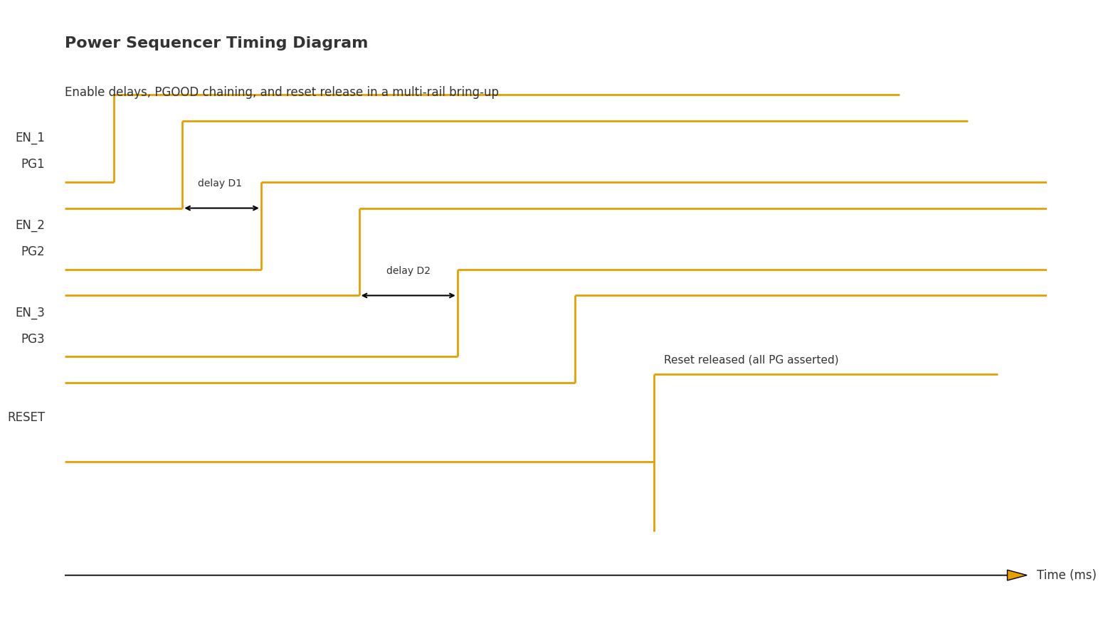
This page focuses strictly on multi-rail power sequencing and supervision: enable delays, PGOOD chaining, reset trees, UV/OV windows with hysteresis, glitch filtering, and fault actions (latch-off vs auto-retry).
Out of scope here: buck/LDO efficiency or loop behavior, inrush/short-circuit/hot-plug protection (see the eFuse/Load Switch page), PMBus tuning/telemetry (see the Digital PMIC page), and system-level rail lists (see the Multi-Rail System PMIC page).
You’ll get a practical workflow: threshold & hysteresis budgeting, bring-up Gantt timing, fault-injection scripts, cold/hot consistency checks, and pre-production gates.
Best for FPGA/SoC platforms, i.MX/edge-AI boards, automotive camera/ECU, and server/mainboard designs.
PMIC Hub
All PMIC topics and sibling pages in one place.
eFuse / Load Switch
Inrush, short-circuit, thermal protection and hot-plug behavior.
Digital PMIC & PMBus
Scripted sequencing, telemetry, limits and run-time adjustments.
Voltage Monitors / Reset IC
Single/multi-channel monitors, reset trees, watchdog roles.
Multi-Rail System PMIC
Power-tree overviews and rail grouping by platform.
Submit your BOM (48h)
Get three pin-compatible options and lead-time choices.
Why Sequencing Matters
Symptoms & Risks
Incorrect or missing sequencing leads to random bring-up, latch-up events, black screens, failed boots, DDR training errors, and even data corruption in storage devices. These issues typically arise when rails power up out of order or when reset is released before all rails have asserted qualified PGOOD.
Dependency Examples
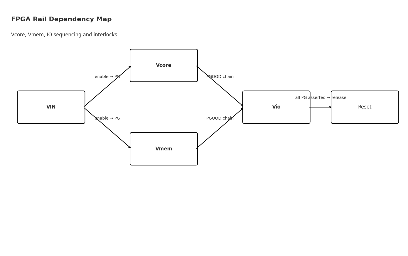
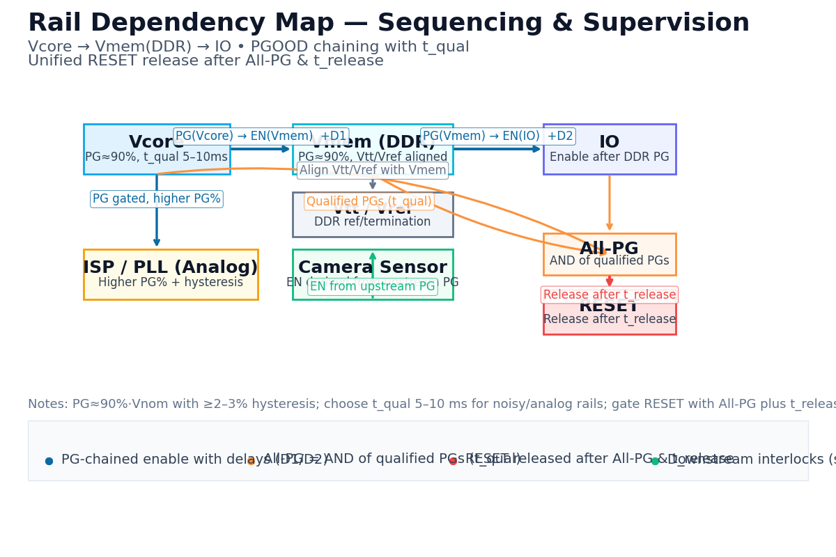
- FPGA/SoC: Vcore → Vmem (DDR) → IO; release RESET only after all PG signals qualify.
- Camera ISP: Analog AVDD should precede digital DVDD; IO/PLL rails depend on core rail PG.
- Server/Mainboard: Vcore/Vmem/Vtt/Vio interlock; Vtt/Vref must be valid relative to Vmem for DDR initialization.
Power-Down Matters Too
Define a power-down sequence to protect memories and peripherals: remove write-side or IO domains first, then core rails, to avoid back-powering and latch-up. Power-down may mirror power-up or prioritize safety with a different ordering.
Typical Failure Cases
- FPGA: IO rises before Vcore → ESD structures back-bias; fix by chaining EN(IO) from PG(Vcore) and releasing RESET only after all PG qualify.
- Camera ISP: AVDD & DVDD start together + PG threshold too low → noise/sparkle; fix by advancing AVDD, delaying DVDD, raising PG threshold to ~90% with 2–3% hysteresis.
- DDR on Mainboard: Vtt/Vref late vs Vmem → training fails; fix by making Vtt/Vref a prerequisite (or in-phase) to Vmem PG and sequencing a safe power-down.
Takeaway 1 — Order + Condition: Not just order; require PG thresholds and time qualification (glitch filtering / hysteresis) before advancing.
Takeaway 2 — Reset Gating: Gate RESET with “All rails PG asserted & qualified”.
Takeaway 3 — Power-Down Strategy: Define a safe shut-down sequence to prevent back-powering and data loss.
Need the full rail list and grouping? See the Multi-Rail System PMIC page (system-level overview; PoL details are out of scope here).
Note: Efficiency, ripple, and loop compensation are handled on the Buck/LDO pages.
What Sequencer & Supervisor Do
Role Overview
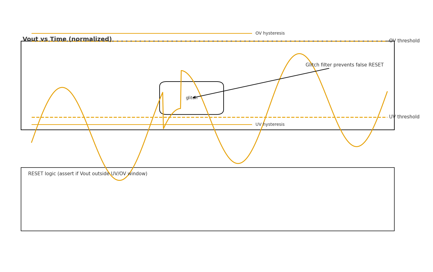
Sequencers orchestrate order, delays, dependencies, and timeouts for multi-rail bring-up and shutdown. Supervisors qualify each rail with UV/OV window thresholds, hysteresis, and glitch filtering, generate PGOOD signals, and assert/release RESET (often with watchdog involvement).
Sequencer Responsibilities
- Scheduling: relative/absolute delays, dependency graphs (A→B→C, AND/OR groups).
- Timeout & halt: stop or rollback on rail timeout or fault; log status.
- Power-down: mirror or safety-first shutdown to protect memories/peripherals.
- I/O: inputs = PG/Fault/Timers; outputs = EN_x, optional RESET gating.
Supervisor Responsibilities
- Window comparator: ensure
Vmin ≤ Vrail ≤ Vmaxwith hysteresis. - PGOOD: assert only when rail is in-window and stable for
t_qual. - RESET: system-level reset aggregation and release timing.
- Watchdog: WDI/WDO supervision; assert RESET or Fault when software stalls.
- Glitch filtering: reject transients; combine with hysteresis to avoid chatter.
Signals & Terms
- PGOOD (Power Good)
- Rail-side “in-spec” indication once voltage is inside the UV/OV window for ≥
t_qual. - RESET
- System reset line (MCU/SoC/FPGA domain). Typically released only after all required PGs qualify.
- UVLO / OV
- Under-voltage lockout and over-voltage thresholds forming a supervisor window for each rail.
- Hysteresis
- Gap between rising and falling thresholds (e.g., UV↑ vs UV↓) that prevents chatter at the decision boundary.
- Glitch Filter
- Time qualification (
t_qual, e.g., a few ms) to ignore short transients before changing PG/RESET state. - Latch-off / Auto-Retry
- Fault actions: hold OFF until manual clear (latch-off) or attempt periodic restarts with back-off (auto-retry).
PGOOD vs RESET: PG is a power-domain quality flag (per-rail or aggregated), while RESET is a system-domain control signal. PGs may flicker with minor dips; RESET is usually debounced, stretched, and released once all required PGs have qualified.
Behavioral Examples
A supervisor asserts PG only when the rail sits inside the UV/OV window and remains stable for t_qual.
Short dips are filtered and do not trigger RESET. RESET is de-asserted after all required PGs qualify, often with an
additional release delay.
Lightweight Engineering Snippets
- PG condition:
PG = (Vrail ≥ V_UV↑) ∧ (Vrail ≤ V_OV↓) ∧ (t_stable ≥ t_qual) - Threshold budgeting:
V_UV↑ ≈ V_nom × (PG% − error_budget)(reference, divider, drift, sampling path)
Need deeper coverage of monitor families and reset trees? Visit Voltage Monitors / Reset IC.
PMBus configuration and telemetry live on the Digital PMIC page to avoid overlap here.
Core Features & Signals
Feature Matrix Overview
Use this matrix as a quick selection board. It aligns parameters with practical guidance without diving into converter topology or PMBus register details.
| Dimension | What it means | Engineering guidance |
|---|---|---|
| Rail Count | Number of rails to orchestrate: 3–4 / 5–12 / 10+. | 3–4: simple sequencer or discrete; 5–12: dedicated sequencer IC; 10+: consider PMIC with built-in sequencer. |
| PG Channels | Per-rail PG, aggregated PG, or programmable mapping. | Prefer per-rail PG with aggregation logic; expose at least one “All-PG” for system RESET gating. |
| Delay Resolution | Step size for enable delays and release timers. | Typical 0.1–10 ms. Ensure timeout window ≥ 3× expected start-up worst-case. |
| Threshold Accuracy | UV/OV window accuracy at 25 °C (±1.0/±1.5/±2.0%) and drift. | Budget reference/divider/drift: set PG% high enough (e.g., ~90%) and keep adequate margin. |
| Window vs Single Threshold | UV+OV window versus only UV or only OV. | Favor window + hysteresis + t_qual to prevent chatter and false resets. |
| Fault Mode | Action on UV/OV/timeout/thermal. | Latch-off for safety-critical/sensitive loads; Auto-retry for intermittent faults with back-off & retry limit. |
| Interfaces | GPIO (pins) vs PMBus (digital control/telemetry). | GPIO = simple, fixed; PMBus = flexible, but firmware-dependent (see Digital PMIC & PMBus). |
| AEC-Q100 | Automotive qualification grade and diagnostics. | Match grade/temperature range and pay attention to diagnostic pins for safety cases. |
| Package & Thermal | Footprint (QFN/TSSOP) and thermal impedance. | Use exposed pad, solid GND, Kelvin sense routing; layout impacts noise and PG accuracy. |
Key Signals & Behaviors
- ENx (out): Sequencer outputs; relative/absolute delays; may be gated by prior PG.
- PGOODx (in/out): Supervisor asserts when rail is in window and stable for
t_qual; sequencer consumes as dependency. - RESET (out): System-domain line; de-assert only after All-PG qualified; can be stretched.
- WDI/WDO (in/out): Watchdog interface; WDO may assert RESET or Fault—arbitrate with power-on logic.
- FAULT (out): Aggregated error reporting; drives latch-off or retry path.
- GPIO (in/out): Mode selects, fault clear, board strapping for variants.
PG vs RESET: PG is a power-domain quality flag (per-rail or aggregated). RESET is a system-domain control signal—debounced and released only after all required PGs qualify.
Accuracy & Timing Granularity
- Threshold budgeting:
V_UV↑ ≈ V_nom × (PG% − error_budget); include reference, divider, amplifier, temperature drift, and sampling path. - Hysteresis & tqual: start with ≥ 2–3% hysteresis and 1–10 ms qualification to suppress chatter and short glitches.
- Delay/timeout: choose resolution/Range that cover worst-case start-up; a timeout ≥ 3× estimated start-up is a good baseline.
Fault Handling Modes
Latch-off
Best for safety-critical/sensitive loads (automotive camera, storage consistency).
- Remains OFF until manual clear or power-cycle.
- Predictable behavior; simplifies failure analysis.
Auto-Retry
Useful for intermittent/external disturbances.
- Use back-off timers; cap retry count to avoid oscillation.
- Monitor thermal rise and log fault counters.
Selection Guidance: Dedicated Sequencer vs PMIC-Integrated
Dedicated Sequencer IC
- Flexible for complex dependency graphs and reuse across projects.
- Distributed placement near loads; independent from regulator choices.
- Trade-off: extra BOM/area; ensure unified RESET aggregation.
PMIC with Built-in Sequencer
- Great for platformized designs with ≥10 rails.
- Smaller footprint and tighter integration with regulators.
- Trade-off: sequencing granularity/threshold options may be constrained.
Three-Question Decision Tree
- ≥ 10 rails and a fixed platform? → Prefer PMIC-integrated.
- Complex dependencies or reuse across diverse boards? → Choose Dedicated Sequencer.
- Need quick tuning in field bring-up? → Prefer parts with GPIO/PMBus (register details on the Digital PMIC page).
Looking for configuration/telemetry details? See Digital PMIC & PMBus. For monitor families and reset trees, visit Voltage Monitors / Reset IC.
Note: PMBus register maps and loop compensation remain out of scope here to avoid overlap.
Timing Design
Method Overview
A robust plan combines relative/absolute delays, PGOOD chaining, a unified RESET release condition, and a defined power-down sequence. Use relative, PG-qualified delays for critical dependencies and absolute delays for low-risk auxiliaries.
Delay Models
Relative (PG-Qualified) Delays
EN_Btriggers afterPG_Aqualifies for ≥t_qualplus delayD_AB.- Use on core→mem→IO chains and sensitive analog domains.
- Combine with a timeout to exit on stalled rails.
Absolute Delays
- Fixed trigger from power-on (e.g.,
T_B = 100 ms). - Good for auxiliaries without strict dependencies.
- Still honor a timeout for bring-up sanity.
RESET gating: RESET_RELEASE = AND(PG_all) ∧ (t ≥ t_release). Stretch RESET to avoid re-asserts from minor PG dips.
Threshold & Hysteresis
Start with PG threshold ≈ 90%·Vnom and hysteresis ≥ 2–3%. Add a qualification
time t_qual (e.g., 1–10 ms) before asserting PG; apply an additional release delay
t_release before de-asserting RESET.
- Budget total error
E_totalfrom reference, divider, amplifier, temperature drift, and sensing path. - PG condition:
PG = (Vrail ≥ V_UV↑) ∧ (Vrail ≤ V_OV↓) ∧ (t_stable ≥ t_qual) - Compute thresholds:
V_UV↑ = V_nom × (PG% − E_total)V_UV↓ = V_UV↑ − ΔH × V_nom(ΔH = hysteresis)- (Optional)
V_OV↓ ≈ V_nom × (PG%_OV + E_total)
V_nom=1.0 V, PG%=90%, ΔH=3%, E_total=2% ⇒
V_UV↑=0.88 V, V_UV↓=0.85 V; with t_qual=5 ms, PG asserts after ≥0.88 V stable for 5 ms.
Cold/Hot & Population Spread
Temperature & Load
- Evaluate −40/25/85 °C (or wider) for PG time, threshold drift, and effective hysteresis.
- Check light/full load start-up spread; beware cross-coupling between rails.
Margins & Redundancy
- Set timeout ≥ 3× worst-case start-up estimate.
- Leave extra PG/hysteresis margin ≥ (E_total + 1–2%).
- Use All-PG plus
t_releaseas a second confirmation for RESET.
Power-Down Strategy
- Mirror the power-up order for simplicity, or
- Safety-first: remove write/IO domains before core to avoid back-powering and data loss (e.g., DDR).
Worksheet Mapping
Map the variables here to the downloadable worksheet fields (Section 11): Rail Name, Vtarget, PG %, Hysteresis %, EN Source, Delay (ms), Timeout (ms), Dependency, Power-down Order, Notes. The right-hand Gantt axis auto-renders bars when Delay and Timeout are filled.
System-level rail lists live on the PMIC for FPGA/SoC page (no PoL efficiency details here).
Fault Handling & Safety
Pipeline: Detect → Arbitrate → Act → Report. Inputs include UV/OV window violations, Timeout, and Thermal warnings. Current-side protection (inrush/short/hot-plug) is handled on the eFuse / Load Switch page.
Detection & Qualification
- UV/OV: window comparators with hysteresis; qualify for
t_qualbefore flagging. - Timeout: a rail fails to reach PG within
T_timeout. - Thermal: on-die or external sensor threshold crossed; treat “critical” above “warning”.
- Debounce: unify sampling cadence; filter glitches to prevent flapping events.
Arbitration & Priority
Recommended priority: OV > Thermal > UV > Timeout.
- Coalesce multiple causes per rail: keep the highest-priority fault.
- Across rails, prioritize “fatal” then “recoverable”. Aggregate for a single policy decision.
Action Models
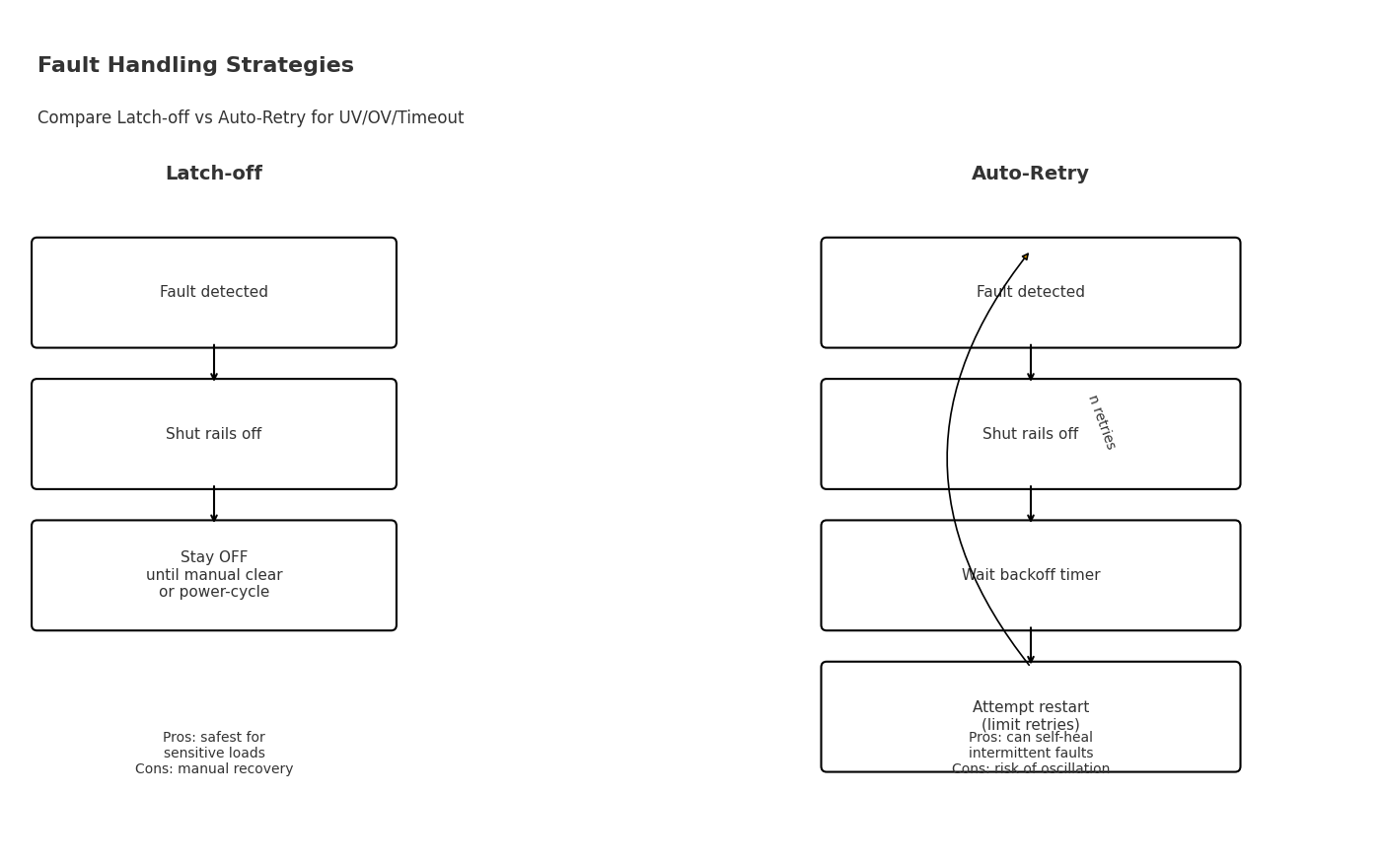
Latch-off
- Shut down affected rails and stay OFF until manual clear or power-cycle.
- Best for safety-critical domains (automotive camera/ECU), memories, and data integrity.
- Pros: predictable, avoids oscillation. Cons: requires human intervention.
Auto-Retry
- Power-down, wait
T_backoff, attempt restart; limit toN_retryattempts. - Useful for intermittent or environment-driven issues.
- Guard against thermal rise and “reboot storms”.
Logging & Telemetry
Minimum fields:
rail_id,fault_type(UV/OV/Timeout/Thermal),count,last_status(OK/Latched/Retrying)last_pg_ms(time to PG),last_temp(optional), and a timestamp if available
Interfaces: GPIO fault pin and manual-clear input; PMBus/UART for structured logs — register/command details live on the Digital PMIC & PMBus page.
Verification & Fault Injection
- UV injection: pull a rail to
V_UV↓ − εfor ≥t_qual→ expect configured action/log. - OV injection: raise to
V_OV↑ + εfor ≥t_qual→ verify priority and reset behavior. - Timeout: extend soft-start beyond
T_timeout→ follow latch/retry path with proper logging. - Thermal: heat to near threshold → check debounce and reporting.
state = IDLE
on power_up:
  if PG_all within T_timeout: goto RUN
  else: goto FAULT

on FAULT:
  log(fault_type, rail_id); pulse GPIO_FAULT
  if policy == LATCH_OFF:
    disable rails; wait_for manual_clear
  if policy == AUTO_RETRY:
    retries = 0
    while retries < N_retry:
      delay(T_backoff); try_restart()
      if PG_all within T_timeout: goto RUN
      retries += 1
    disable rails; wait_for manual_clear

on RUN:
  monitor UV/OV/Thermal with hysteresis + t_qual
  if violation: goto FAULT
Current-limit, inrush, and hot-plug protections are covered on the eFuse / Load Switch page to avoid overlap.
Topologies & Integration
Overview
Three viable routes depending on rail count, complexity, and platform reuse. Pick one and apply the layout/signal guidelines below.
Discrete Supervisor + RC (3–4 rails, cost-sensitive)
- Makeup: voltage monitor/reset IC(s) + RC delays + simple logic (diode-OR / gates).
- Pros: lowest BOM, easy sourcing, intuitive debug.
- Limits: delay/threshold tunability; RC tolerance × temp drift; poor scalability.
- Notes: aggregate & stretch RESET; ensure PG↔EN level compatibility (open-drain pull-ups).
Dedicated Sequencer IC (5–12 rails, mid complexity)
- Makeup: sequencer + monitors (or built-in PG sampling).
- Pros: flexible dependencies, timeouts, logging; distributed placement near loads.
- Trade-offs: bigger BOM/area; define logging/clear-fault I/O (GPIO/PMBus).
- Notes: central “All-PG” aggregation & RESET gating; align timing references.
PMIC-Integrated Sequencer (10+ rails, platformized)
- Makeup: multi-rail PMIC with sequencing/supervision, sometimes PMBus.
- Pros: compact, platform reuse, thermal/layout centralized.
- Limits: fixed granularity for thresholds/delays; coupling between rails; migration cost.
- Notes: keep noise-sensitive analog rails separated; consider dedicated LDO for PLL/analog.
Mini decision tree: ≤4 rails & cost sensitive → Discrete · 5–12 rails & complex deps → Dedicated Sequencer · ≥10 rails & platformized → PMIC-Integrated.
Layout Notes
Sampling & Returns
- Kelvin sense at the load; return directly to the supervisor/comparator ground.
- Keep high
di/dtreturn paths away from PG/RESET and sense traces. - Separate analog grounds (PLL/ADC) from noisy digital returns when feasible.
Placement & Decoupling
- Place monitors/sequencers near their critical rails; minimize loop area.
- Ensure at least one decoupler between regulator output and sense node.
- Low ESR can change ramp shape; re-check
t_qualand PG margins.
Signal Integration
PG & RESET
- Open-drain PG: pull up to the target logic domain; aggregate an All-PG and then debounce/stretch.
- RESET is system-domain; arbitrate with watchdog (WDO) and make it “first low, last released”.
- Match voltage domains (1.8/3.3/5 V); add level shifting/buffers if needed.
Pull-ups & Fanout
- Pull-ups that are too small cause chatter; too large slow the rise. Tune for signal integrity.
- RESET fanout is limited by line capacitance; buffer or segment if many loads are present.
- Keep PG/RESET away from high
dv/dtnodes; use inner layers and guard traces if necessary.
Noise & Filtering
- Hysteresis: start from 2–3% (larger for analog rails) and pair with
t_qual(1–10 ms). - RC tolerances: 10–20% plus temp drift; use device-integrated filters for critical chains.
- EMI/crosstalk: avoid long parallel runs; cross at right angles; shield with solid GND.
Validation Hooks (DFT/Bring-up)
- Expose test pads for PG/EN/RESET; break out the All-PG aggregation node.
- Add injection points (jumpers/series Rs) to force UV/OV/Timeout for Section 5 procedures.
- If PMBus is present, reserve minimal commands for log read/clear and threshold/delay tweaks (details on Digital PMIC page).
Need a low-noise analog rail? See LDO. Handling inrush/short/hot-plug? See eFuse / Load Switch.
Design Workflow
Overview
A seven-step, execution-ready flow for sequencing & supervision. Each step lists inputs, actions, outputs, and acceptance criteria.
- Inputs BOM / SoC power table / constraints
- Actions Enumerate Rail / Vtarget / Group; draw core→mem→IO deps
- Outputs Initial rail + dependency sheet
- Acceptance 100% coverage incl. power-down hypothesis
- Inputs Dependency graph, est. start-up times
- Actions Use PG→EN relative delays for critical chains; absolute for auxiliaries; gate RESET by All-PG & trelease
- Outputs Timing draft (PNG), EN/PG/RESET axes
- Acceptance No cyclic deps;
T_timeout ≥ 3×worst-case start-up
- Inputs Vtarget, error & drift budget
- Actions Start PG ≈
90%·Vnom; hysteresis ≥2–3%; computeV_UV↑/V_UV↓; sett_qual - Outputs Threshold/hysteresis table + error budget
- Acceptance
PG% − E_total − ΔH/2leaves positive margin
- Inputs Floorplan / partitions / noise domains
- Actions Prefer PG chaining + relative delays; define central All-PG & RESET aggregation
- Outputs Signal map (EN/PG/RESET/FAULT fanout)
- Acceptance Single RESET authority; level/fanout constraints met
- Inputs Soft-start profile, fault model
- Actions Set
T_timeoutper rail; choose Latch-off or Auto-Retry withT_backoff&N_retry - Outputs Policy table (rail / fault / action)
- Acceptance Meets safety goals; avoids reboot storms
- Inputs −40/25/85 °C, multiple builds
- Actions Capture power-up/down waveforms; record PG latency & RESET release
- Outputs Waveform gallery + statistics
- Acceptance All corners meet PG/RESET criteria; no false timeouts
- Inputs Injection fixtures/scripts
- Actions Follow Section 5 procedures; log type/rail/count/timestamps
- Outputs Injection results + issue list
- Acceptance Actions & logs match policy; system recovers stably
Artifacts & Owners
- HW — dependency graph, timing sketch, threshold table, signal fanout
- FW — watchdog/reset coordination, fault logging & reporting interface
- Test/QA — corner validation, fault injection scripts, pass criteria
- PM/Lead — checklist sign-off (version/date/signature)
Tools & Downloads
Checklist (PDF) — aligns to the eight chapters including pre-production checks.
Worksheet (Excel) — columns map to: Rail Name, Vtarget, PG %, Hysteresis %, EN Source, Delay (ms), Timeout (ms), Dependency, Power-down Order, Notes; right-side Gantt auto-renders bars.
Review Gates
Gate D1 (Pre-freeze)
- Steps 1–4 complete; drawings & tables consistent
- Risks closed; dependencies resolved; RESET authority defined
Gate D2 (Pre-proto validation)
- Steps 5–6 complete; corner waveforms pass
- Policy & logging interfaces aligned
Gate D3 (Pre-MP)
- Step 7 fault injection complete; full checklist signed
- Worksheet archived with final timing and thresholds
Work top-down with clear acceptance at each step. When ready, grab the templates below.
Application Cards
Each card lists only sequencing & supervision essentials. Power-stage (PoL) selection is covered on sibling pages.
FPGA / SoC
Sequence & reset-only essentials (PoL details elsewhere).
- Sequence map: Vcore → Vmem (DDR) → IO.
PG(Vcore)→EN(Vmem), thenPG(Vmem)→EN(IO). - RESET: gate by All-PG & trelease; align with JTAG/BOOT pins in the reset tree.
- DDR rails: ensure Vtt/Vref valid before or in phase with Vmem.
- Thresholds: PG ≈ 90%·Vnom, hysteresis ≥ 2–3%,
t_qual5–10 ms (use upper bound for DDR/PLL). - Fault policy: proto → limited Auto-Retry; production/safety domains → Latch-off.
- Validation: confirm DDR training only after PG(mem); inject UV on Vmem and verify action/log.
Takeaway: Release RESET only after All-PG; treat DDR/Vtt/Vref as first-class dependencies.
See examples on PMIC for FPGA/SoC and PLL-friendly rails on LDO.
i.MX / Edge AI
Group rails by function; interlock downstream peripherals.
- Sequence map: power Core/DDR first, then IO/CSI/DSI; gate camera/ISP peripherals with upstream PG.
- Interlocks: sensor/VCM/flash EN derives from SoC/ISP PG; avoid back-powering via IO lines.
- Thresholds: analog/PLL rails may use PG 92–94% with larger hysteresis;
t_qual5–10 ms. - Timeouts: mandatory for bring-up (detect missing peripherals or stalls).
- Fault policy: peripherals → limited Auto-Retry; main SoC → Latch-off.
- Validation: verify IO last-to-release; hot-plug of camera should not flap system RESET.
Takeaway: Chain camera-domain power to SoC/ISP PG and enforce strict timeouts.
Handle inrush/short on eFuse / Load Switch; scripted sequences on Digital PMIC & PMBus.
Automotive Camera / ECU
Safety-first sequencing with ASIL-oriented supervision.
- Sequence map: self-check/MCU → sensor/ISP → comm/IO; release system only after All-PG & trelease.
- Thresholds: AEC-Q100 parts; PG ≥ 90%, hysteresis ≥ 3%,
t_qual≈ 10 ms (with transient immunity). - Transients: qualify against ISO-7637/ESD conditions to avoid false RESET.
- Fault policy: default Latch-off; allow scoped Auto-Retry in non-safety domains with back-off & retry cap.
- Reset redundancy: dual RESET paths or cross-monitors for fail-safe behavior.
- Validation: cold crank and voltage sags; UV/OV/Timeout/thermal injections with consistent logging.
Takeaway: Prefer latch-off and redundant resets; size hysteresis/filters for automotive transients.
Explore monitor families on Voltage Monitors / Reset IC and load protection on eFuse / Load Switch.
Part Selection Shortlist
Brand-neutral guidance. We list series types and key dimensions so you can narrow options without turning this page into a product catalog.
Selection Dimensions
| Dimension | What it means | Engineering guidance |
|---|---|---|
| Rail Count / PG Mapping / Delay Resolution | Rails to orchestrate (3–4 / 5–12 / 10+), per-rail vs aggregated PG, delay step & timeout ceiling. | 3–4 → discrete monitor + RC; 5–12 → dedicated sequencer; 10+ → PMIC-integrated. Prefer per-rail PG with an “All-PG” aggregation. |
| Threshold Accuracy & Drift | UV/OV window accuracy (±1.0/±1.5/±2.0% @25 °C) and temperature drift. | Budget total error; set PG ≈ 90%·Vnom with adequate margin; tighten for analog/PLL rails. |
| Window vs Single-Threshold | Window = UV+OV bounds; single = only UV or only OV. | Favor window + hysteresis (≥2–3%) + t_qual (1–10 ms) to prevent chatter and false resets. |
| Fault Mode | Action on UV/OV/timeout/thermal. | Latch-off for safety/critical loads; Auto-Retry for intermittent faults with back-off & retry cap. |
| Interfaces | GPIO pins vs PMBus configuration/telemetry. | GPIO = simple & fixed. PMBus = flexible but firmware-dependent (details on the Digital PMIC & PMBus page). |
| AEC-Q100 | Automotive qualification (grade, temp, diagnostics). | Match grade to safety goals; prefer parts with diagnostic pins and robust transient immunity. |
| Package & Thermal | QFN/TSSOP, exposed pad, θJA, layout constraints. | Use exposed pad and solid GND; plan Kelvin sense and keep sense/PG lines away from high di/dt returns. |
Quick tip: ≥10 rails & platformized → PMIC-integrated. Complex cross-board reuse → dedicated sequencer. High accuracy on a few sensitive rails → window supervisor + sequencer hybrid.
Shortlist by Series Type (Brand-Neutral)
Dedicated Multi-Rail Sequencer IC
- Typical 5–12 rails; PG-in / EN-out; timeout & fault aggregation.
- Delay resolution ~0.1–10 ms; optional GPIO / some with PMBus.
- Choose for complex dependency graphs and distributed placement.
- Check debounce/stretch capability and minimal logging/clear-fault I/O.
- Packages: QFN/TSSOP; ensure RESET aggregation node is central.
Window Voltage Supervisor (1/2/4/6-Ch)
- ±1.0–2.0% accuracy; hysteresis and glitch qualification (
t_qual). - Open-drain PG/RESET; optional watchdog.
- Select by channels, drift, hysteresis span, and
t_qualrange. - Automotive variants with AEC-Q100 and diagnostic pins available.
Reset / Watchdog Supervisor
- Programmable reset timeout; WDI/WDO for software liveness.
- Arbitrate with power-domain RESET; check polarity/drive strength.
- Level compatibility across 1.8/3.3/5 V domains.
PMIC with Integrated Sequencer
- 10+ rails with grouped sequencing and aggregated PG.
- Footprint-efficient for platform designs; some offer PMBus/telemetry.
- Check threshold/delay granularity and family pin-compatible options.
- Consider rail coupling and sensitive-rail isolation (PLL/analog → LDO).
Supervisors for Low-Noise Analog / PLL
- Larger hysteresis and longer
t_qualto suppress ripple/phase noise effects. - Low drift; pair with dedicated LDO and Kelvin sense routing.
- Prefer separate analog ground return to minimize PG chatter.
Conversion
Brand-neutral recommendation: send your rail list, timing sketch, and constraints — we’ll return 3 pin-compatible options matched to your dimensions (rail count, PG mapping, accuracy, fault mode, interface, AEC-Q100, package).
PMBus register maps and converter topologies live on sibling pages to keep this shortlist focused.
FAQs
Structured answers with quick rules and in-page anchors for deeper dives.
How do I pick UV/OV thresholds and hysteresis without chattering?
Short answer: Start with PG ≈ 90%·Vnom, hysteresis ΔH ≥ 2–3%, and qualification t_qual = 1–10 ms (noisier rails → upper bound).
Why: Margin against total error E_total; compute V_UV↑ = V_nom × (PG% − E_total) and V_UV↓ = V_UV↑ − ΔH·V_nom.
See also: Threshold & Hysteresis, Accuracy & Timing.
What’s the difference between PGOOD and RESET, and who releases first?
Short answer: PGOOD is a power-domain quality flag per rail/aggregate; RESET is a system-domain gate. RESET de-asserts only after All-PG qualifies plus t_release.
Practice: Gate boot on AND(PG_all) and stretch RESET to avoid flaps from brief PG dips.
See also: What Sequencer & Supervisor Do, Key Signals.
When should I prefer latch-off vs auto-retry, and how to size limits?
Short answer: Safety/data-critical → Latch-off. Intermittent/environmental → Auto-Retry with back-off and retry cap (e.g., 3–5).
Tip: Monitor thermal; escalate to latch-off after retry budget to avoid reboot storms.
See also: Fault Handling Modes, Fault Pipeline.
Can I safely daisy-chain PGOOD across 12+ rails without a central gate?
Guidance: Use PG-qualified relative delays for critical paths, but still aggregate an All-PG for RESET gating and system readiness.
Reason: Deep chains raise debug latency and error propagation; a central All-PG shortens fault detection and simplifies release.
See also: Delay Models, Topologies Overview.
How do I balance low-noise analog rails with strict sequencing needs?
Short answer: Raise PG% (e.g., 92–94%), enlarge hysteresis, and lengthen t_qual; route Kelvin sense and isolate noisy returns.
Layout: Separate analog/PLL grounds and avoid cross-talk near PG sense dividers.
See also: Noise & Filtering, LDO.
What changes for cold start, hot-plug, or brown-outs regarding timing and thresholds?
Checklist: Re-measure start-up times across −40/25/85 °C; set T_timeout ≥ 3× worst-case; increase hysteresis and t_qual for hot-plug noise.
Protection: Handle inrush/short on current-side devices (eFuse/Load Switch) to avoid false PG trips.
See also: Cold/Hot & Spread, eFuse / Load Switch.
PMIC-integrated sequencer vs dedicated sequencer IC—how do I decide?
Rule of thumb: ≥10 rails with fixed platform → PMIC-integrated. Complex reuse/varied boards → dedicated sequencer for flexibility.
Trade-offs: PMIC saves area but may limit granularity; dedicated parts add BOM but ease cross-project migration.
See also: Selection Guidance, Topologies.
How should the watchdog interact with RESET and the MCU/SoC boot flow?
Practice: Let WDO assert RESET but arbitrate so that power-good rules dominate release. Keep RESET “first low, last released.”
Coordination: Align boot pins (JTAG/BOOT) with the reset tree and All-PG.
See also: Key Signals, Workflow Steps.
How do I budget threshold error: reference, divider tolerance, drift, sensing path?
Method: Quadrature sum E_total ≈ √(E_ref²+E_div²+E_amp²+E_temp²+E_sense²); then set V_UV↑ = V_nom × (PG% − E_total).
Tip: Keep extra margin ≈ E_total + 1–2% for population spread.
See also: Threshold & Hysteresis, Accuracy & Timing.
What’s a safe power-down order to protect DDR/NAND data and avoid back-powering?
Rule: Mirror power-up or use safety-first: shut down write/IO domains before cores; keep RESET asserted through the sequence.
Why: Prevents latch-up and data corruption, especially for memory subsystems.
See also: Power-Down Strategy.
How do I inject UV/OV/timeout faults on the bench and define pass criteria?
Procedure: Force V_UV↓ − ε or V_OV↑ + ε ≥ t_qual; extend soft-start beyond T_timeout. Verify action (latch/retry) and logs.
Pass: Behavior matches policy; system recovers stably after clear/retry.
See also: Verification & Fault Injection.
What AEC-Q100 specifics matter for supervisors in automotive cameras/ECUs?
Focus: Grade/temperature, diagnostic pins, transient immunity; prefer larger hysteresis and t_qual ≈ 10 ms.
Policy: Default to latch-off; restrict retries to non-safety domains and monitor thermal rise.
See also: Automotive Card, Core Features.
Is 90%·Vnom always right for PGOOD? When do 92–94% and longer t_qual help?
Guidance: 90% fits most digital rails; use 92–94% with longer t_qual on analog/PLL/ISP rails to suppress ripple.
Note: Re-check error budget and ensure RESET still releases with margin.
See also: Threshold Rules, i.MX / Edge AI.
How many absolute vs relative delays should I use, and how to size timeouts?
Answer: Prefer PG-qualified relative delays for dependencies; keep absolute delays for auxiliaries. Use T_timeout ≥ 3× worst-case start-up.
Reason: Relative delays track process/temperature spread; absolute ones don’t.
See also: Delay Models, Workflow Step 2/5.
Resources & RFQ
Download the ready-to-use checklist and worksheet, then submit your BOM to receive three pin-compatible options within 48 hours.
Multi-Rail Bring-Up Checklist (PDF)
Covers: requirements → rail/dependency table → thresholds/hysteresis → timing/delays → fault scripts → cold/hot/population validation → fault injection → pre-MP checks.
- 30+ check items with Signature Date Version
- Printable & e-sign ready • aligns with Review Gates
Spec: PDF • v1.0 • last updated this release
Download PDFPower-Up/Down Timing Worksheet (Excel)
Columns: Rail Name | Vtarget | PG% | Hysteresis% | EN Source | Delay(ms) | Timeout(ms) | Dependency | Power-down Order | Notes.
- Right-side Gantt: 0–1000 ms, 50 ms steps (conditional formatting)
- Maps to Timing Worksheet variables
Spec: XLSX • v1.0 • includes example rows
Download ExcelBrand-neutral recommendation: share your rail list and timing sketch — we’ll return 3 pin-compatible options matched to your constraints (rails, PG mapping, accuracy, fault policy, interface, AEC-Q100, package).